OSD335x Lesson 2: Bringing Up a Custom Bare-Bones Linux PCB
Published On: May, 8, 2018 By: Eshtaartha Basu | Updated: November 16, 2018 by Cathleen Wicks
1 Bringing Up a Custom Bare-Bones Linux PCB
1.1 Introduction
In this article, we will finalize the Lesson 2 board design and bring up the manufactured printed circuit board (PCB). This will allow us to explore new applications with our completed design and use the completed design as a starting point for future application specific designs.
The software operating system needed for the projects we will be running on the board is based on Linux. Because the OSD3358 is based on the Sitara® AM335x ARM® Cortex® A8 processor from TI, there are many Linux distributions available. The one we will be using is the Linux image from BeagleBoard.org®. This Linux image is based on the Debian distribution of Linux and is robust and supported by a strong open source community. The BeagleBoard.org® Foundation is a US-based non-profit existing to provide education in and collaboration around the design and use of open-source software and hardware in embedded computing.
Prerequisite
This article is a part of the broader OSD335x Reference Design Lesson 2 series which consists of a sequence of articles designed to help you build the bare minimum circuitry required to boot Linux on the OSD335x. We recommend reading the article OSD335x Lesson 2: Adding Non-Volatile Storage before this one. This article builds upon the foundation outlined in it.
All design files for this lesson can be downloaded here.
Table of Contents
1Bringing Up a Custom Bare-Bones Linux PCB
1.1Introduction
1.2Finalizing the Lesson 2 Design
1.2.1Adding LEDs
1.2.2Finalizing the silkscreen
1.2.3Expected outcome
1.3PCB Manufacturing
1.4Bringing up the PCB
1.5Booting Linux
1.6Demo Application
![]()
![]() A PDF version of this Lesson as well as the entire OSD335x Design Tutorial can be downloaded here.
A PDF version of this Lesson as well as the entire OSD335x Design Tutorial can be downloaded here.

1.2 Finalizing the Lesson 2 Design
In this design, we have added USB ports and non-volatile storage. Besides the need to clean up the silkscreen on the board to fully document the design on the PCB, it is also useful to add some user defined LEDs that can be used to monitor the health of the PCB during operation.
1.2.1 Adding LEDs
During operation, it is important that a design provide feedback to a user so that they can understand if there are any issues with the operating state. One convenient way to provide feedback is with LEDs. Also, Linux provides an easy method, through the device tree, to connect LEDs to system events, such as CPU and memory activity.
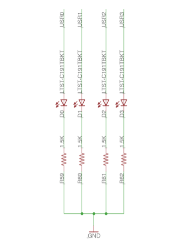
By default, the Linux image from BeagleBoard.org® or RED Linux image supports 4 user-defined (USR) LEDs. These LEDs must be connected to four GPIO pins as defined in the device tree in order to have the indicated functionality. The GPIOs corresponding to user LEDs and their default operation is summarized in Table 1.
| LED | AM335x GPIO Signal | Function |
|---|---|---|
| USR0 | GPMC_A05 | Blinks in heartbeat pattern |
| USR1 | GPMC_A06 | Blinks during SD Card activity |
| USR2 | GPMC_A07 | Blinks during CPU activity |
| USR3 | GPMC_A08 | Blinks during eMMC activity |
You can see the mapping of these pins to their respective system function in the Linux device tree. The snippet of the device tree used trigger LEDs is shown in Figure 1.
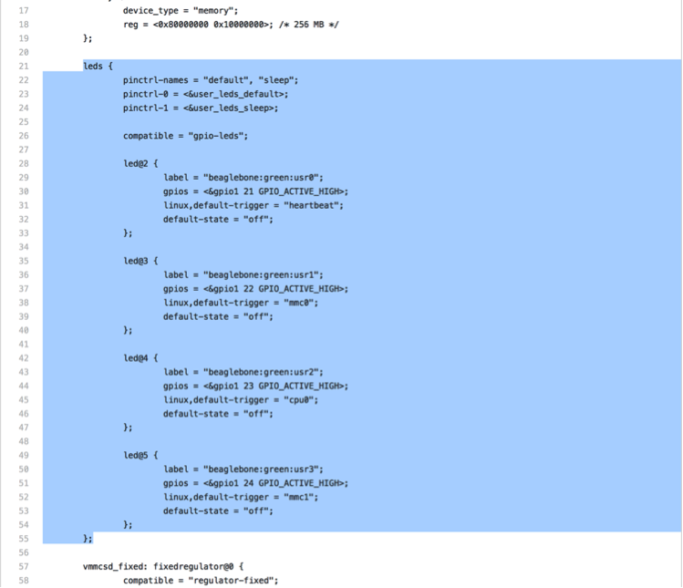
In the above code snippet, which can be found in dtb-rebuilder 1
- pinctrl parameters are used to setup pin multiplexing for LEDs. You can find more information at https://www.kernel.org/doc/Documentation/devicetree/bindings/pinctrl/pinctrl-bindings.txt.
- compatible property is used to bind the gpio-leds driver to the LEDs. See https://www.kernel.org/doc/Documentation/devicetree/bindings/leds/leds-gpio.txt.
- label property is used to uniquely identify the LED.
- gpios property is used to assign a particular GPIO for the LED and also define its active state.
- linux, default-trigger is used to set a system event as trigger to the LED. See https://www.kernel.org/doc/Documentation/devicetree/bindings/leds/common.txt to know more about available triggers and their assignment.
- default-state determines the initial state of the LED.
To find more information about modifying the device tree for your custom board, please refer to our forthcoming articles on Linux.
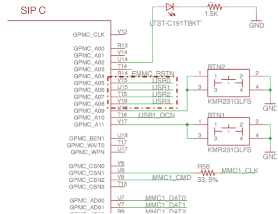
The LED circuit can be built and added to Lesson 2 design as shown in Figure 2 and Figure 3.
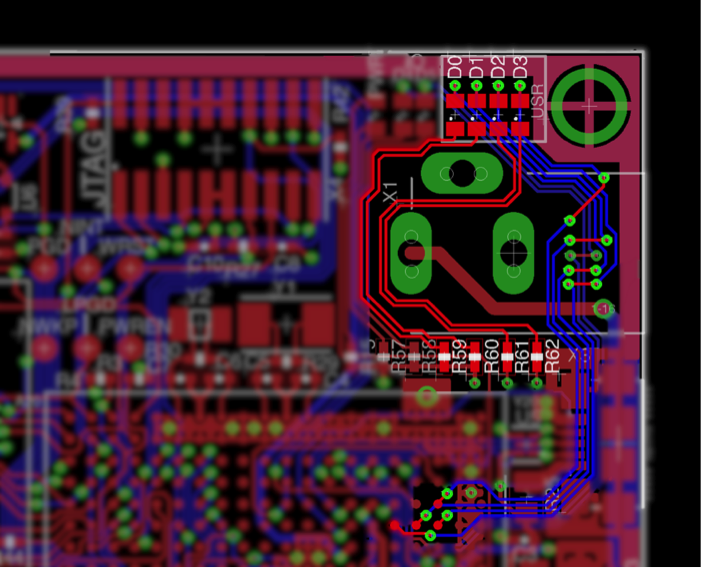
The LED circuit layout can be built as shown in Figure 4.
1.2.2 Finalizing the silkscreen
Once the design is complete, the silk screen should be finalized to fully document the PCB. The steps needed to finalize silkscreen are discussed as part of the Finalizing the silkscreen Section of OSD335x Peripheral Circuitry Article from Lesson 1.
1.2.3 Expected outcome
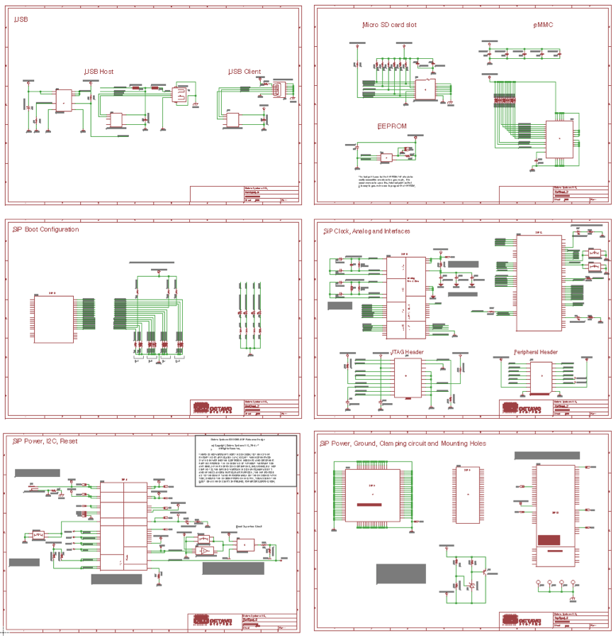
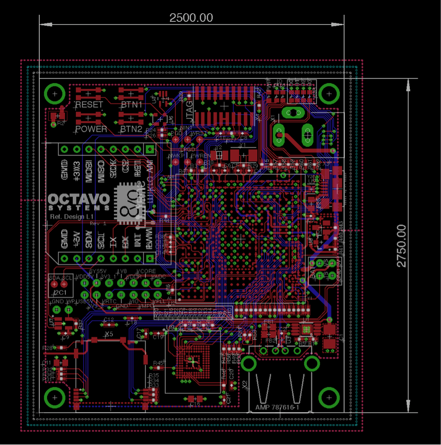
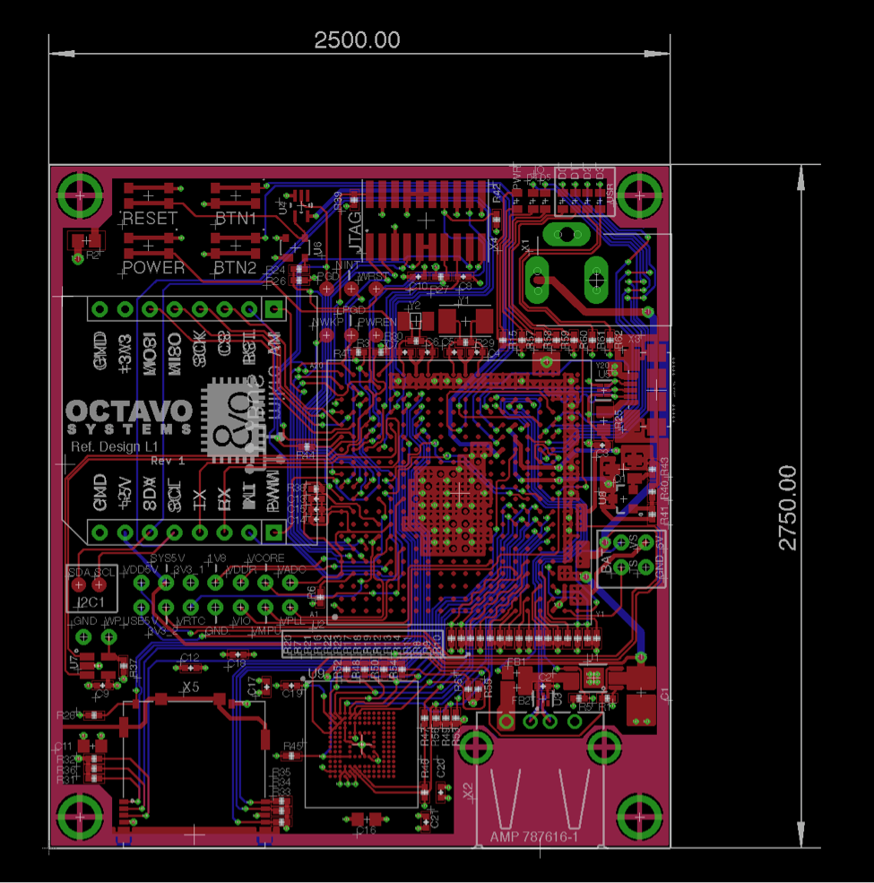
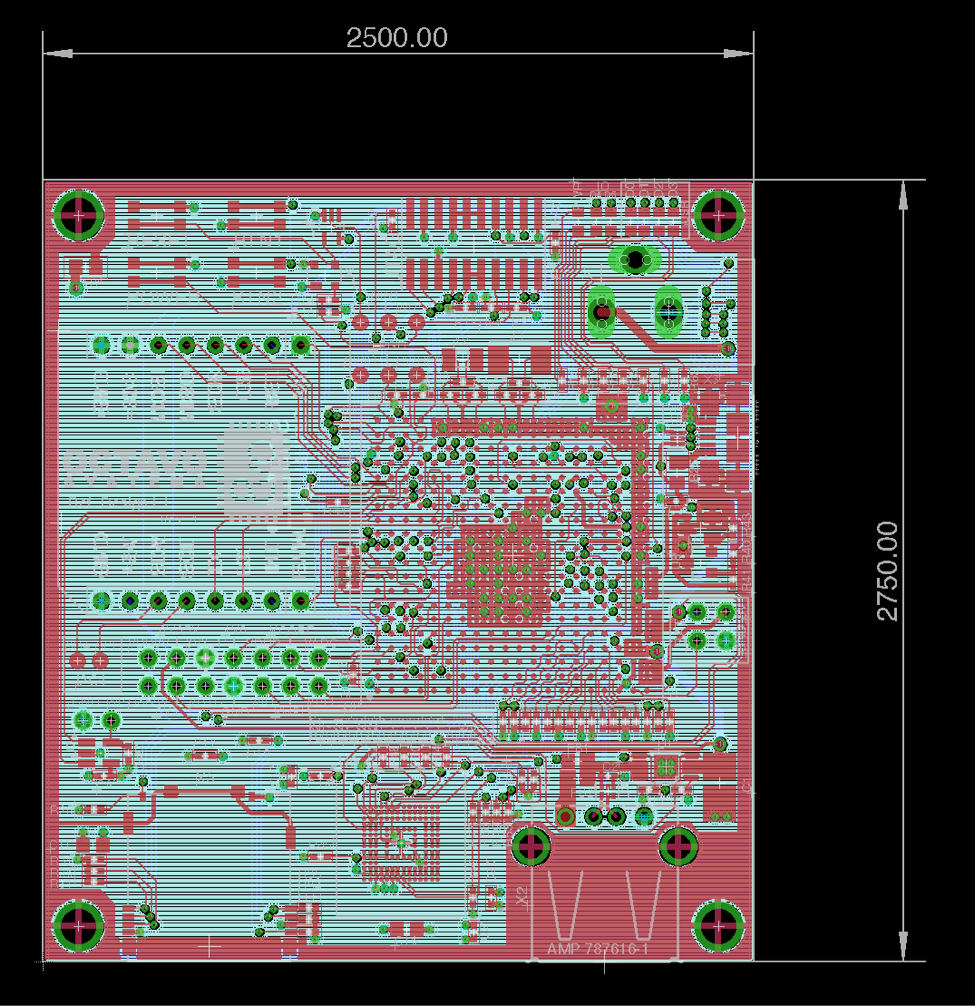
Now that we have completed the Lesson 2 design, the completed schematic should look similar to Figure 5 and completed layout should look similar to Figure 6, Figure 7 and Figure 8.
1.3 PCB Manufacturing
To have the Lesson 2 design manufactured, please follow the procedure discussed in the PCB order process Section of OSD335x Peripheral Circuitry Article from Lesson 1.
1.4 Bringing up the PCB
Once you have the manufactured Lesson 2 design, please follow the procedure discussed in the Basic board bring-up Section of OSD335x Bare Minimum Board Boot Process Article from Lesson 1.
1.5 Booting Linux
The Lesson 2 design can boot any of the Linux images from BeagleBoard.org® or the RED Linux image. However, the system functionality will be slightly different since the Lesson 2 design does not have the same peripheral set as other reference designs. The getting started page of BeagleBoard.org® will help you flash the uSD card, eMMC and install necessary drivers. Although these instructions are intended for one of the BeagleBoard.org® development boards, they can also be used to get started with the Linux image from BeagleBoard.org® or the RED Linux image on the Lesson 2 design.

One thing to be careful about when using the above images: the U-Boot bootloader within the images looks for a board id in an EEPROM attached to the I2C0 bus. The board id is used by U-Boot to identify the board so that the on-board hardware components can be initialized properly before booting the Linux kernel. If suitable information is not found in the EEPROM (e.g. the EEPROM is blank or has not yet been programmed) or if EEPROM is absent on the board, then U-Boot will not boot Linux kernel. Unfortunately, this check occurs before the serial console has been initialized so no boot messages will be displayed on the UART0 serial console making the board look like it is not working properly. We have developed an application note, EEPROM During Boot, specifically to guide you through any potential EEPROM configuration issues during boot.
This application note will discuss how the board ID is used in U-Boot, how to modify U-Boot to ignore the board ID, and how to program the board ID in an EEPROM either before boot or within U-Boot. Your preferred method to program the board ID, depends on the hardware in your system. For example, the tutorial board can boot from a microSD card, then modifying U-Boot to program the board ID will likely be your preferred method. If you have an external I2C programmer, that programming method is also covered in the application note. Finally, if you would like to program the EEPROM over USB from a host PC, software is provided in the associated zip file.
1.6 Demo Application
Once Linux is running, we can now explore different applications on the Lesson 2 design. For example, we can use a Motion Click to detect motion and alert a user by flashing some LEDs. The Motion Click, an add-on board from MikroElektronica, is built around a pyroelectric sensor that pulls the interrupt pin high whenever it senses motion of objects that emit infrared, such as living bodies. The demo app consists of a simple bash script which polls the status of the interrupt pin of Motion Click when it is plugged into the peripheral header and blinks LEDs D4 and D5 whenever motion is detected. The demo app can be downloaded here.
To run the demo app on the Lesson 2 board:
- Copy the demo app to the uSD card or eMMC of the Lesson 2 board.
- Make the demo app file executable by using the command:
1 | chmod +x DemoApp_L2.sh |
- Run the demo app with the command:
1 | sh ./DemoApp_L2.sh |
(1) dtb-rebuilder is developed and maintained by Robert C Nelson
*****
| << Return to “OSD335x Lesson 2 Adding Non-Volatile Storage” | Continue to “OSD335x Lesson 2: Linux Boot Process with the OSD335x” >> |
