OSD335x Lesson 2: Linux Device Tree Overlay
Published On: May, 31, 2018 By: Eshtaartha Basu | Updated: July 31, 2018 by Cathleen Wicks
1 Linux Device Tree Overlay
1.1 Introduction
Since the adoption of the Device Tree standard to describe embedded Linux systems, there has been one major limitation: the static nature of device trees (please find more information on Linux device trees here). Device trees could not cope with changes in non-discoverable hardware, such as modifications to pin muxing, during run time. However, most modern embedded systems support adding and removing non-discoverable hardware during run time. This made it difficult to define the full hardware configuration statically at boot time in a device tree. Pantelis Antoniou, an active Linux kernel developer, implemented a solution to this issue using Device Tree Overlays (DTOs). The idea was to be able to dynamically insert a fragment of a device tree into a live device tree to update the hardware configuration of the system. For example, a fragment could change the status property of a device node from “disabled” to “okay” and then the device corresponding to that node would be created.
A device tree overlay is a file that consists of one or more device tree fragments that describe changes to the system hardware. This article will help you become familiar with device tree overlays by explaining the structure through an example, building a device tree overlay for the peripheral header of the Lesson 2 board, and then adapting the generic overlay for an example Click board.
Prerequisite
This article is a part of the broader OSD335x Reference Design Lesson 2 series which consists of a sequence of articles designed to help you build the bare minimum circuitry required to boot Linux on the OSD335x. We recommend reading the article OSD335x Lesson 2: Linux Device Tree before this one. This article builds upon the foundation outlined in it.
All PCB design files for this lesson can be downloaded here.
Lesson 2 Device Tree files can be downloaded here.
Table of Contents
1Linux Device Tree Overlay
1.1Introduction
1.2Understanding Device Tree Overlays
1.3Generic Device Tree Overlay for the Peripheral Header
1.4Adapting the Generic Device Tree Overlay for a Specific Click Board
1.5Building and Using a Device Tree Overlay
1.6Checking if the Device Tree Overlay works as intended
![]()
![]() A PDF version of this Lesson as well as the entire OSD335x Design Tutorial can be downloaded here.
A PDF version of this Lesson as well as the entire OSD335x Design Tutorial can be downloaded here.

1.2 Understanding Device Tree Overlays
The structure of a device tree overlay is a direct extension of a device tree. First, let’s understand the structure by looking at the PB-I2C1-MPU-9DOF-CLICK.dts device tree overlay file. This overlay was written for the MPU 9DOF Click board which can be attached to the headers of the BeagleBoard.org ® PocketBeagle®. Since the PocketBeagle® uses the OSD335x-SM device (which is very similar to the OSD335x), it will be easy to leverage this overlay for the Lesson 2 board (The PB-I2C1-MPU-9DOF-CLICK.dts file is available for download here).
1 2 3 4 5 6 7 8 9 10 11 12 13 14 15 16 17 18 19 20 21 22 23 24 25 26 27 28 29 30 31 32 33 34 35 36 37 38 39 40 41 42 43 44 45 46 47 48 49 50 51 52 53 54 55 56 57 58 59 60 61 62 63 | /* * Copyright (C) 2017 Robert Nelson <robertcnelson@gmail.com> * * This program is free software; you can redistribute it and/or modify * it under the terms of the GNU General Public License version 2 as * published by the Free Software Foundation. */ /dts-v1/; /plugin/; #include <dt-bindings/board/am335x-bbw-bbb-base.h> #include <dt-bindings/gpio/gpio.h> #include <dt-bindings/pinctrl/am33xx.h> / { fragment@0 { target = <&am33xx_pinmux>; __overlay__ { mpu9150_pins: pinmux_mpu9150_pins { pinctrl-single,pins = < AM33XX_IOPAD(0x0824, PIN_INPUT | MUX_MODE7 ) /* (T10) gpmc_ad9.gpio0[23] INT */ >; }; }; }; fragment@1 { target = <&ocp>; __overlay__ { P2_03_pinmux { status = "disabled"; }; }; }; fragment@2 { target = <&i2c1>; __overlay__ { status = "okay"; #address-cells = <1>; #size-cells = <0>; mpu9150@69 { compatible = "invensense,mpu9150"; reg = <0x69>; interrupt-parent = <&gpio0>; interrupts = <23 1>; i2c-gate { #address-cells = <1>; #size-cells = <0>; ax8975@c { compatible = "ak,ak8975"; reg = <0x0c>; }; }; }; }; }; }; |
The above overlay code consists of three major parts:
First, the overlay begins with tokens (shown below). The first token indicates the file version and the second one indicates that this file is a plugin (i.e. an overlay).
1 2 | /dts-v1/; /plugin/; |
Next, the tokens are followed by include statements. This is where required header files are included in the overlay to add symbol definitions and macros.
1 2 3 | #include <dt-bindings/board/am335x-bbw-bbb-base.h> #include <dt-bindings/gpio/gpio.h> #include <dt-bindings/pinctrl/am33xx.h> |
Finally, the fragments describe the functional changes to the device tree for the overlay, starting from the root node ( / ):
The first fragment of the overlay (fragment@0) is used to set the P2_03 pin of the PocketBeagle (i.e. the GPMC_AD9 pin, bit 23 of the GPIO0 peripheral of the AM335x) to GPIO input mode. When the MPU 9DOF Click board is connected to the PocketBeagle, the INT pin of the Click connects to the P2_03 pin. Therefore, the pin must be configured so that the PocketBeagle can receive interrupt signals from the MPU 9DOF Click. To configure the pin, the target property is used to specify the device tree node that needs to be overlaid. In this case, the am33xx_pinmux node is specified to alter the pin muxing of the AM335x IO. The properties listed in the __overlay__ node will be overlaid on the original properties of the target device tree node.
1 2 3 4 5 6 7 8 9 10 11 | fragment@0 { target = <&am33xx_pinmux>; __overlay__ { mpu9150_pins: pinmux_mpu9150_pins { pinctrl-single,pins = < AM33XX_IOPAD(0x0824, PIN_INPUT | MUX_MODE7 ) /* (T10) gpmc_ad9.gpio0[23] INT */ >; }; }; }; |
The second fragment of the overlay (fragment@1) is then used to disable the current functionality associated with the P2_03 pin. Currently in the PocketBeagle device tree, the P2_03 pin is configured to use the bone-pinmux-helper driver in the OCP (On Chip Peripheral) node (see am335x-pocketbeagle.dts). Therefore, the driver must be disabled to ensure that the P2_03 pin is available to receive interrupts from the Click board.
1 2 3 4 5 6 7 8 9 | fragment@1 { target = <&ocp>; __overlay__ { P2_03_pinmux { status = "disabled"; }; }; }; |
The third fragment (fragment@2) is used to enable the I2C communication with the Click board. The Click board communicates over the I2C1 bus. Therefore, the I2C1 interface needs to be enabled by setting the status property of the i2c1 node to okay. Also, all the required information of the IC on the MPU 9DOF Click board, such as the manufacturer name, IC name, device address on the I2C bus, etc. must be supplied in this fragment so the kernel can load the appropriate drivers. The device tree bindings for MPU-9150 IC on the MPU 9DOF Click can be found here.
1 2 3 4 5 6 7 8 9 10 11 12 13 14 15 16 17 18 19 20 21 22 23 24 | fragment@2 { target = <&i2c1>; __overlay__ { status = "okay"; #address-cells = <1>; #size-cells = <0>; mpu9150@69 { compatible = "invensense,mpu9150"; reg = <0x69>; interrupt-parent = <&gpio0>; interrupts = <23 1>; i2c-gate { #address-cells = <1>; #size-cells = <0>; ax8975@c { compatible = "ak,ak8975"; reg = <0x0c>; }; }; }; }; }; |
1.3 Generic Device Tree Overlay for the Peripheral Header
The Lesson 2 board has a peripheral header that supports removable Click boards. Similar to the device tree overlay in the previous section, a generic device tree overlay (osd335x_L2_generic.dts) can be built for the Lesson 2 board’s peripheral header as shown below (The overlay can also be downloaded here.
The overlay has three parts like the previous example, however, there are more fragments to enable the different peripherals used by the header. The first fragment is used to configure the pin muxing for all the interfaces on the peripheral header such as SPIO0, UART0, I2C1 and GPIO pins. The second, third and fourth fragments enable the I2C1, SPI0 and UART0 interfaces, respectively, and provide an outline to add device tree binding information corresponding to the type of click board that you will use.

1 2 3 4 5 6 7 8 9 10 11 12 13 14 15 16 17 18 19 20 21 22 23 24 25 26 27 28 29 30 31 32 33 34 35 36 37 38 39 40 41 42 43 44 45 46 47 48 49 50 51 52 53 54 55 56 57 58 59 60 61 62 63 64 65 66 67 68 69 70 71 72 73 74 75 76 77 78 79 80 81 82 83 84 85 86 87 88 89 90 91 92 93 94 95 96 97 98 99 100 101 102 103 104 105 106 107 | /* * Copyright (C) 2017 2017 Octavo Systems - http://www.octavosystems.com/ * * This program is free software; you can redistribute it and/or modify * it under the terms of the GNU General Public License version 2 as * published by the Free Software Foundation. */ /dts-v1/; /plugin/; #include <dt-bindings/board/am335x-bbw-bbb-base.h> #include <dt-bindings/gpio/gpio.h> #include <dt-bindings/pinctrl/am33xx.h> / { fragment@0 { target = <&am33xx_pinmux>; __overlay__ { pwm_pins: pinmux_pwm { pinctrl-single,pins = < AM33XX_IOPAD(0x0964, PIN_OUTPUT | MUX_MODE0 ) /* (C18) ECAP0_IN_PWM0_OUT */ >; }; int_n_rst_pins: pinmux_int_rst { pinctrl-single,pins = < AM33XX_IOPAD(0x0824, PIN_INPUT | MUX_MODE7 ) /* (T10) gpmc_ad9 MBUS_INT */ AM33XX_IOPAD(0x0820, PIN_OUTPUT | MUX_MODE7 ) /* (U10) gpmc_ad8 MBUS_RST */ >; }; i2c1_pins: pinmux_i2c1 { pinctrl-single,pins = < AM33XX_IOPAD(0x0968, PIN_INPUT_PULLUP | MUX_MODE3 ) /* (E18) I2C1_SDA/UART0_CTSN */ AM33XX_IOPAD(0x096C, PIN_INPUT_PULLUP | MUX_MODE3 ) /* (E17) I2C1_SCL/UART0_RTSN */ >; }; spi0_pins: pinmux_spi0 { pinctrl-single,pins = < AM33XX_IOPAD(0x0950, PIN_INPUT | MUX_MODE0 ) /* (A17) spi0_sclk.spi0_sclk */ AM33XX_IOPAD(0x0954, PIN_INPUT | MUX_MODE0 ) /* (B17) spi0_d0.spi0_d0 */ AM33XX_IOPAD(0x0958, PIN_INPUT | MUX_MODE0 ) /* (B16) spi0_d1.spi0_d1 */ AM33XX_IOPAD(0x095c, PIN_INPUT | MUX_MODE0 ) /* (A16) spi0_cs0.spi0_cs0 */ >; }; }; }; fragment@1 { target = <&i2c1>; __overlay__ { status = "okay"; pinctrl-names = "default"; pinctrl-0 = <&i2c1_pins>; /* Add device tree bindings * for your I2C1 device here. * */ }; }; fragment@2 { target = <&spi0>; __overlay__ { status = "okay"; pinctrl-names = "default"; pinctrl-0 = <&spi0_pins>; /* Add device tree bindings * for your SPI device here. * */ }; }; fragment@3 { target = <&uart0>; __overlay__ { status = "okay"; pinctrl-names = "default"; pinctrl-0 = <&uart0_pins>; /* Add device tree bindings * for your UART device here. * */ }; }; }; |
1.4 Adapting the Generic Device Tree Overlay for a Specific Click Board
When you decide to use a specific Click board with the Lesson 2 board, it is straight-forward to modify the generic device tree overlay created in the previous section, versus writing one from scratch, in order to support the Click board. Taking the MPU 9DOF Click example from Section 1.2, you would only need to add the MPU9150 device tree binding information under fragment@1 since MPU 9DOF Click uses the I2C bus for communication. The new device tree overlay (osd335x_L2_generic_i2c1.dts) would look like this (content that is different from generic DTO is highlighted):
1 2 3 4 5 6 7 8 9 10 11 12 13 14 15 16 17 18 19 20 21 22 23 24 25 26 27 28 29 30 31 32 33 34 35 36 37 38 39 40 41 42 43 44 45 46 47 48 49 50 51 52 53 54 55 56 57 58 59 60 61 62 63 64 65 66 67 68 69 70 71 72 73 74 75 76 77 78 79 80 81 82 83 84 85 86 87 88 89 90 91 92 93 94 95 96 97 98 99 100 101 102 103 104 105 106 107 108 109 110 111 112 113 114 115 116 117 118 119 120 | /* * Copyright (C) 2017 Octavo Systems - http://www.octavosystems.com/ * * This program is free software; you can redistribute it and/or modify * it under the terms of the GNU General Public License version 2 as * published by the Free Software Foundation. */ /dts-v1/; /plugin/; #include <dt-bindings/board/am335x-bbw-bbb-base.h> #include <dt-bindings/gpio/gpio.h> #include <dt-bindings/pinctrl/am33xx.h> / { fragment@0 { target = <&am33xx_pinmux>; __overlay__ { pwm_pins: pinmux_pwm { pinctrl-single,pins = < AM33XX_IOPAD(0x0964, PIN_OUTPUT | MUX_MODE0 ) /* (C18) ECAP0_IN_PWM0_OUT */ >; }; int_n_rst_pins: pinmux_int_rst { pinctrl-single,pins = < AM33XX_IOPAD(0x0824, PIN_INPUT | MUX_MODE7 ) /* (T10) gpmc_ad9 MBUS_INT */ AM33XX_IOPAD(0x0820, PIN_OUTPUT | MUX_MODE7 ) /* (U10) gpmc_ad8 MBUS_RST */ >; }; i2c1_pins: pinmux_i2c1 { pinctrl-single,pins = < AM33XX_IOPAD(0x0968, PIN_INPUT_PULLUP | MUX_MODE3 ) /* (E18) I2C1_SDA/UART0_CTSN */ AM33XX_IOPAD(0x096C, PIN_INPUT_PULLUP | MUX_MODE3 ) /* (E17) I2C1_SCL/UART0_RTSN */ >; }; spi0_pins: pinmux_spi0 { pinctrl-single,pins = < AM33XX_IOPAD(0x0950, PIN_INPUT | MUX_MODE0 ) /* (A17) spi0_sclk.spi0_sclk */ AM33XX_IOPAD(0x0954, PIN_INPUT | MUX_MODE0 ) /* (B17) spi0_d0.spi0_d0 */ AM33XX_IOPAD(0x0958, PIN_INPUT | MUX_MODE0 ) /* (B16) spi0_d1.spi0_d1 */ AM33XX_IOPAD(0x095c, PIN_INPUT | MUX_MODE0 ) /* (A16) spi0_cs0.spi0_cs0 */ >; }; }; }; fragment@1 { target = <&i2c1>; __overlay__ { status = "okay"; pinctrl-names = "default"; pinctrl-0 = <&i2c1_pins>; #address-cells = <1>; #size-cells = <0>; mpu9150@69 { compatible = "invensense,mpu9150"; reg = <0x69>; interrupt-parent = <&gpio0>; interrupts = <23 1>; i2c-gate { #address-cells = <1>; #size-cells = <0>; ax8975@c { compatible = "ak,ak8975"; reg = <0x0c>; }; }; }; }; }; fragment@2 { target = <&spi0>; __overlay__ { status = "okay"; pinctrl-names = "default"; pinctrl-0 = <&spi0_pins>; /* Add device tree bindings * for your SPI device here. * */ }; }; fragment@3 { target = <&uart0>; __overlay__ { status = "okay"; pinctrl-names = "default"; pinctrl-0 = <&uart0_pins>; /* Add device tree bindings * for your UART device here. * */ }; }; }; |
You can also directly download the osd335x_L2_generic_i2c1.dts device tree overlay file here.
1.5 Building and Using a Device Tree Overlay
The process to compile a device tree overlay is similar to the process to compile a device tree as discussed in Section 1.3 of Linux Device Tree article. For the OSD335x Family of devices, Robert Nelson’s Device Tree Rebuilder can be used to build the DTO. You can download it here. The steps to build the DTO are as follows:
- Copy the osd335x_L2_generic_i2c1.dts file to the dtb-rebuilder/src/arm/ directory.
- Build the file using make command.
- Once the build process completes, the osd335x_L2_generic_i2c1.dtb file will be available in the dtb-rebuilder/src/arm/ directory. Change the extension of the file to .dtbo (i.e., osd335x_L2_generic_i2c1.dtbo) to make sure the linux kernel recognizes it as an overlay.
- Copy the osd335x_L2_generic_i2c1.dtbo file to the /lib/firmware directory (You will have to run this command as root)
- Open the uEnv.txt file in the /boot directory using your favorite text editor and set custom_cape = osd335x_L2_generic_i2c1.dtbo as shown in Figure 1. Save and close the file.
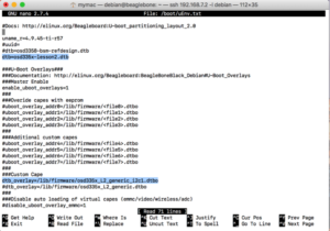

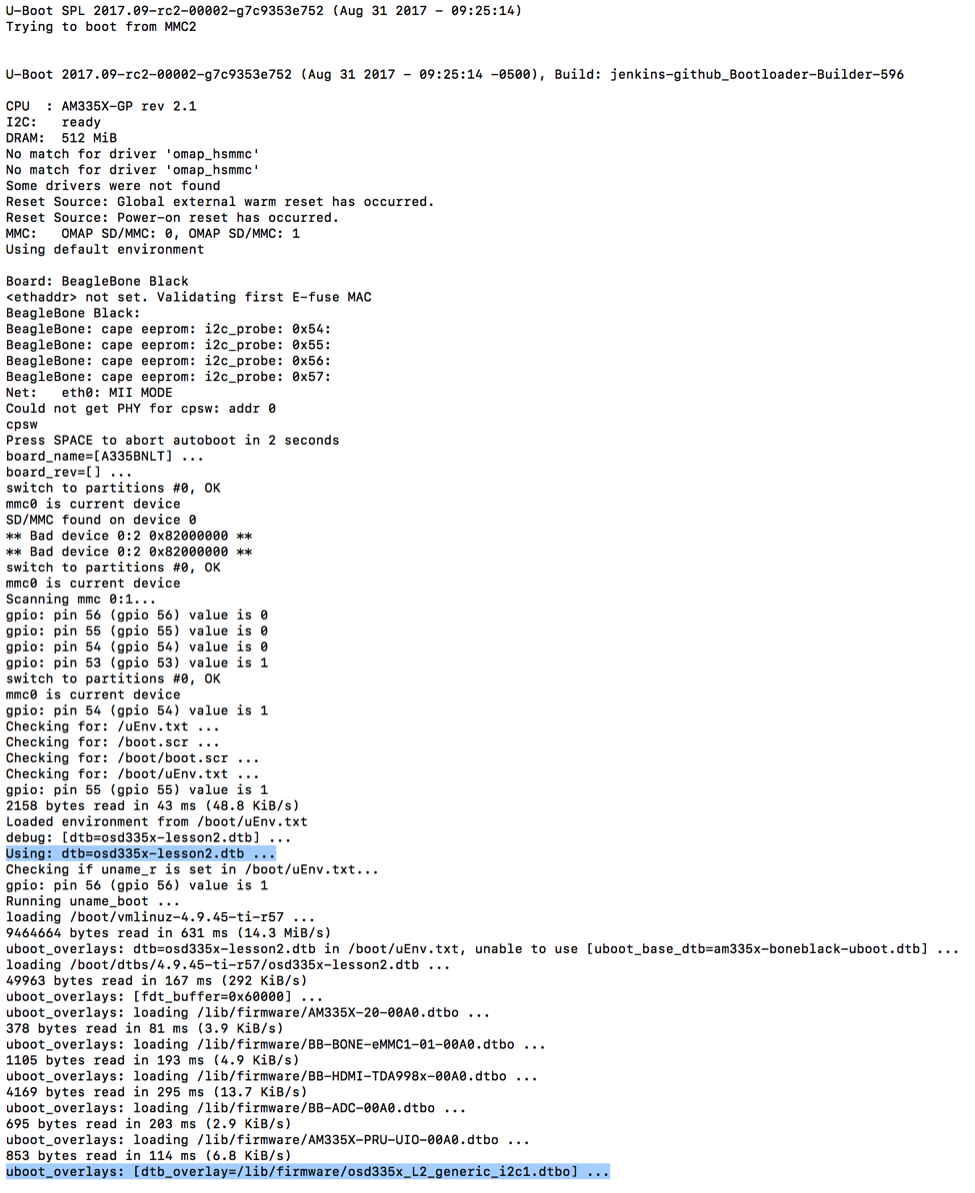
Figure 1 Setting Device Tree Overlay - Reboot the board. If you monitor the boot messages on the UART0 serial console, it will display the name of the device tree and device tree overlays that were loaded during boot-up as shown in Figure 2.

You can now login to Debian (default username = debian, password = temppwd).
1.6 Checking if the Device Tree Overlay Works as Intended
If the new DTO works as intended, the Linux kernel should recognize the MPU 9DOF Click and load appropriate drivers. From the command line, you can check if appropriate driver has been loaded for the IC on the MPU 9DOF by listing the i2c bus drivers (as shown in Figure 3) using the command
1 | ls /sys/bus/i2c/drivers |
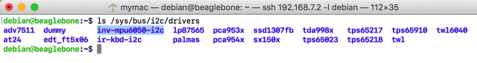
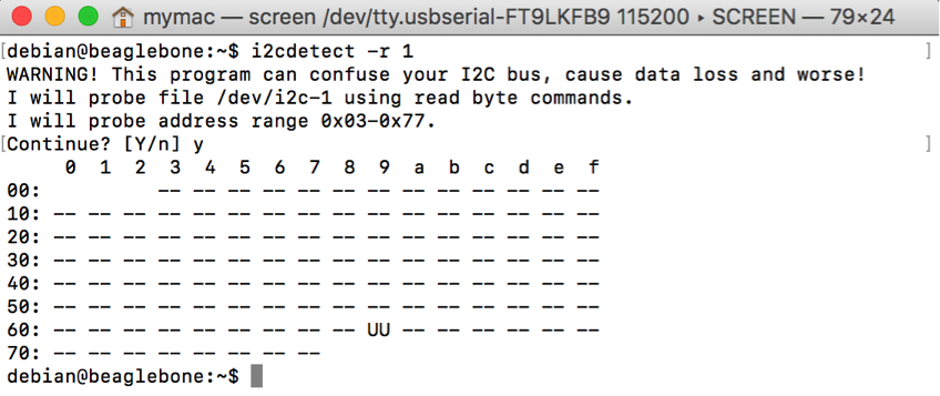
If the Invensense MPU6050 I2C driver appears, you know that the device was properly configured and the correct driver was loaded. Also, given a kernel driver was loaded for MPU 9DOF click, you should see UU (Unit Unavailable) on the I2C1 bus at address 0x69 when the i2cdetect command is used to scan the I2C1 bus for devices as shown in Figure 4. When a kernel driver manages a device, it will not allow i2cdetect to probe the device. Therefore, you will see UU when scanned versus 69, if the correct driver was not loaded.
Finally, you can check if the MPU 9DOF Click appears as an IIO (Industrial IO) device by searching for IIO devices in IIO devices directory as shown in Figure 5.

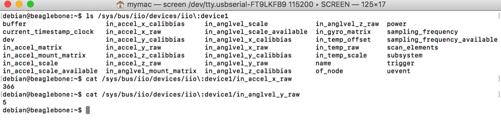
If all the above checks succeed, the device is working properly and you can directly access the accelerometer, compass and other values from the MPU 9DOF Click using Sysfs (more on Sysfs here). Most of the readable registers of the MPU 9DOF Click are available as files under the IIO device directory for the Click (iio:device1, in the picture below. However, the device number maybe different in your system) as shown in Figure 6.
For any questions or concerns, you can reach us at: https://octavosystems.com/forums/
We’d like to thank lewing@isc.tamu.edu and The GIMP for permission to use the ‘Tux’ Linux image used in our social media about this post
| << Return to “OSD335x Lesson 2 : Linux Device Tree” |
