OSD335x EEPROM During Boot
Published On: June, 13, 2018 By: Erik Welsh | Updated: January 9, 2020 by Cathleen Wicks
 When creating a new embedded Linux design, getting a printed circuit board (PCB) to boot for the first time can have many unique challenges. These challenges can be hardware related: incorrect connections, improper voltages, bad component values, etc. or software related: incorrect device tree, improper drivers, bad configuration values etc. One common challenge: how to properly load and configure software drivers during boot. It is important for the software running on the new design to recognize the unique set of peripherals and components used on the PCB so that the drivers can be properly loaded and configured. This can be accomplished in many different ways: pulling GPIO pins, programming hardware fuses, storing values in non-volatile memory, etc. This is an area where having non-volatile storage, like EEPROM, either inside a System-in-Package, as in the OSD335x-SM, or on the board can help. The Linux images from BeagleBoard.org used for the OSD335x Family of devices, identify designs by a unique code, a board ID, that is stored within an EEPROM attached to the I2C0 bus. This board ID is then used within U-Boot to properly configure the system.
This article will discuss: how the board ID is used in U-Boot (Section 3); how to modify U-Boot to ignore the board ID (Section 4); and how to program the board ID in an EEPROM either before boot (Section 6) or within U-Boot (Section 5). Your preferred method to program the board ID, depends on the hardware in your system. For example, if you can boot from a microSD card, then modifying U-Boot to program the board ID (either Section 4.2 or Section 5) might be your preferred method. Similarly, if you have an external I2C programmer, you would prefer the programming method outlined in Section 6.1. If you would like to program the EEPROM over USB from a host PC (Section 6.2), software has been provided in the associated zip file and can also be found in Sections 8 and 9.
Get updates to this application note and all of our documentation
"*" indicates required fields
Table of Contents
1.Introduction
2.Revision History
3.Understanding the Board ID
4.Modifying U-Boot to Ignore the Board ID
4.1Hard-Coding the Board ID
4.2Recognizing a “Blank” Board ID
5.Programming the Board ID Within U-Boot
6.Programming the Board ID Outside of U-Boot
6.1Using an External I2C Programmer
6.2Over USB From a Host PC
6.2.1Installing the Tools
6.2.2Compiling the Binary
6.2.3Programming the Device
7.References
8.Appendix A: hsi2cEeprom.c
9.Appendix B: hsi2cEeprom.lds
![]()
![]() A PDF version of this App Note can be found here.
A PDF version of this App Note can be found here.
![]()
![]() The code files associated with this App Note can be found here.
The code files associated with this App Note can be found here.
2 Revision History
| Revision Number | Revision Date | Changes | Author |
|---|---|---|---|
| 1 | 6/12/2018 | Initial Release | E. Welsh |
| 2 | 8/12/2019 | Added caveats for Windows compilation under section 6.2.2 | E. Basu |

3 Understanding the Board ID
A board ID can be used for many different functions:
- Distinguishing between different hardware designs
- Allowing inventory management and board tracking, such as differentiating between manufacturers
- Identifying and tracking failures for yield analysis
- Compatibility checking for software
- Encoding board revisions for debug
During boot, it is especially important to distinguish between different hardware designs so that software drivers can be properly configured and loaded. As part of the Linux boot process for the OSD335x Family of devices, U-Boot uses the board ID to determine the printed circuit board (board) on which it is running. This makes U-Boot more flexible and allows a single U-Boot image to be used for many different development platforms. You can see that there are many functions defined in the U-Boot file “./board/ti/am335x/board.h” that are used to control what functions are performed during the boot process (you can find the files by viewing the U-Boot source code, see reference section on page 19). For example, the following function is used to determine if the board is the Beagleboard.org® PocketBeagle®:
1 2 3 4 | static inline int board_is_pb(void) { return board_ti_is("A335PBGL"); } |
This function uses a common board detect infrastructure defined in “./board/ti/common/board_detect.c” and “./board/ti/common/board_detect.h” to determine the board. The board detect infrastructure in turn relies on a specific data structure, a ti_am_eeprom struct. This structure is found at the beginning of an EEPROM on an I2C bus (I2C0 in the case of the AM335x devices):
1 2 3 4 5 6 7 8 9 10 11 12 13 14 15 16 17 18 19 20 21 22 23 | /** * struct ti_am_eeprom - This structure holds data read in from the * AM335x, AM437x, AM57xx TI EVM EEPROMs. * @header: This holds the magic number * @name: The name of the board * @version: Board revision * @serial: Board serial number * @config: Reserved * @mac_addr: Any MAC addresses written in the EEPROM * * The data is this structure is read from the EEPROM on the board. * It is used for board detection which is based on name. It is used * to configure specific TI boards. This allows booting of multiple * TI boards with a single MLO and u-boot. */ struct ti_am_eeprom { unsigned int header; char name[TI_EEPROM_HDR_NAME_LEN]; char version[TI_EEPROM_HDR_REV_LEN]; char serial[TI_EEPROM_HDR_SERIAL_LEN]; char config[TI_EEPROM_HDR_CONFIG_LEN]; char mac_addr[TI_EEPROM_HDR_NO_OF_MAC_ADDR][TI_EEPROM_HDR_ETH_ALEN]; } __attribute__ ((__packed__)); |
In the definition above, the header field is a “magic number”, i.e. a constant, TI_EEPROM_HEADER_MAGIC, with a value of 0xEE3355AA. This structure can be generically referred to as a “board ID” even though it has many different pieces of information. If you read the contents of an EEPROM from the Octavo Systems development board OSD3358-SM-RED, you can see that it follows the above data structure format:
1 2 3 | Address Value ASCII Value 00000000 AA 55 33 EE 41 33 33 35 42 4E 4C 54 4F 53 30 30 .U3.A335BNLTOS00 00000010 00 00 00 00 00 00 00 00 00 00 00 00 FF FF FF FF ................ |
Unfortunately, the reliance on the board ID during U-Boot can cause problems when first booting a board after manufacturing. By default, all EEPROMs are initially unprogrammed (i.e. all bytes have a value of 0xFF) when placed on a board. Therefore, when U-Boot first comes up and reads the unprogrammed board ID, it will read a value that does not match any board causing the software to hang because U-Boot is unable to know how to configure any peripheral to continue the boot. Unfortunately, the software hang occurs before the U-Boot console is active which can be mistaken for hardware bring-up problems (i.e. power is applied to the board, but nothing happens).
To mitigate this issue, you can either modify U-Boot to ignore the board ID information within the EEPROM (i.e. hard code the board ID), or you can program the EEPROM to have the correct board ID information for the given system.
4 Modifying U-Boot to Ignore the Board ID
One way to overcome an unprogrammed EEPROM is to modify U-Boot itself so that either the board ID is ignored by U-Boot or that the value of an unprogrammed EEPROM is recognized as a “blank” board. While modifying U-Boot can be a good short-term solution to work around this condition, it is not necessarily a good long-term solution to have U-Boot either ignore the board ID or for the board to be recognized as “blank”. Doing this in a production software image can be problematic in the case that revisions of the system have components that must be handled differently during boot. It also limits the reusability of the production software image across multiple products. Therefore, it is recommended to only ignore the board ID during the prototyping phase of a design and to program the EEPROM with a valid board ID during production (See Section 5).
To modify U-Boot, you first must be familiar with the process needed to build U-Boot. You can find instructions on how to do this at https://eewiki.net/display/linuxonarm/BeagleBone+Black Once you are familiar with the process, there are two methods you can follow to update U-Boot to bypass the board ID checks.
4.1 Hard-Coding the Board ID
In this first method, you can manually modify U-Boot to hard code a function within “./board/ti/am335x/board.h” so that the board has a fixed identity (i.e. the board ID is “hard coded”). For example, to make U-Boot always identify the board as “BeagleBone® Black”, you will need to make the following modification:
1 2 3 4 5 | static inline int board_is_bone_lt(void) { // return board_ti_is("A335BNLT"); -- Hard code board ID to BeagleBone Black return 1; } |
By returning “1” (i.e. true), this function will make U-Boot believe that the board is BeagleBone® Black and follow the boot process for BeagleBone® Black. If this works for your system (i.e. you have similar components to the BeagleBone® Black for booting, like an eMMC on MMC1 and an SD card on MMC0), then you can use this to bypass the board ID check.
4.2 Recognizing a “Blank” Board ID
Another method to ignore the board ID, is to update U-Boot to recognize the unprogrammed EEPROM value as “blank”. To do this, a patch has been created that can help with this process. As part of the U-Boot build process there are two patches that must be downloaded and applied to the U-Boot code base:
1 2 | wget -c https://rcn-ee.com/repos/git/u-boot-patches/v2018.03/0001-am335x_evm-uEnv.txt-bootz-n-fixes.patch wget -c https://rcn-ee.com/repos/git/u-boot-patches/v2018.03/0002-U-Boot-BeagleBone-Cape-Manager.patch |
In addition to these patches, another patch can be downloaded that will configure U-Boot to recognize the unprogrammed EEPROM value as a “blank” board and potentially program the EEPROM with a board ID. You can find this patch at:
https://github.com/RobertCNelson/Bootloader-Builder/raw/master/patches/v2018.03-rc1/0002-NFM-Production-eeprom-assume-device-is-BeagleBone-Bl.patch
If you look at the patch, you can see how the files in U-Boot will be modified to ignore the board ID by recognizing the unprogrammed EEPROM as a “blank” (i.e. “A335BLNK”) board and then potentially program a board ID value into the EEPROM. If you look at lines 153 to 167 of the patch:
1 2 3 4 5 6 7 8 9 10 11 12 13 14 15 | @@ -190,6 +190,14 @@ "setenv fdtfile am335x-boneblack.dtb; " "fi; " "fi; " + "if test $board_name = A335BLNK; then " + "if test -e mmc 0:1 /boot/.eeprom.txt; then " + "load mmc 0:1 ${loadaddr} /boot/.eeprom.txt;" + "env import -t ${loadaddr} ${filesize};" + "echo Loaded environment from /boot/.eeprom.txt;" + "run eeprom_program; " + "fi;" + "setenv fdtfile am335x-boneblack-emmc-overlay.dtb; fi; " "if test $board_name = BBBW; then " "setenv fdtfile am335x-boneblack-wireless.dtb; fi; " "if test $board_name = BBG1; then " |
You can see that if the board is “blank” (i.e. “A335BLNK”), then the boot process will check to see if the file “/boot/.eeprom.txt” exists in the root file system of the boot image. If it does, then it will automatically run the eeprom_program command, defined in 0001-am335x_evm-uEnv.txt-bootz-n-fixes.patch, utilizing the variables set in the “/boot/.eeprom.txt” file. If you look at the eeprom_program command (lines 1607 to 1617 of 0001-am335x_evm-uEnv.txt-bootz-n-fixes.patch):
1 2 3 4 5 6 7 8 9 10 11 | + "eeprom_program=" + "if test $board_eeprom_header = bbb_blank; then " + "run eeprom_dump; run eeprom_blank; run eeprom_bbb_header; run eeprom_dump; reset; fi; " + "if test $board_eeprom_header = bbbl_blank; then " + "run eeprom_dump; run eeprom_blank; run eeprom_bbb_header; run eeprom_bbbl_footer; run eeprom_dump; reset; fi; " + "if test $board_eeprom_header = bbbw_blank; then " + "run eeprom_dump; run eeprom_blank; run eeprom_bbb_header; run eeprom_bbbw_footer; run eeprom_dump; reset; fi; " + "if test $board_eeprom_header = os00_blank; then " + "run eeprom_dump; run eeprom_blank; run eeprom_bbb_header; run eeprom_os00_footer; run eeprom_dump; reset; fi; " + "if test $board_eeprom_header = beaglelogic_blank; then " + "run eeprom_dump; run eeprom_blank; run eeprom_beaglelogic; run eeprom_dump; reset; fi; " |
You can see that depending on the value of the variable board_eeprom_header, the appropriate board ID value will be programmed into the EEPROM. As of this writing, the acceptable values for board_eeprom_header are:
- board_eeprom_header=bbb_blank
- board_eeprom_header=bbbl_blank
- board_eeprom_header=bbbw_blank
- board_eeprom_header=os00_blank
- board_eeprom_header=beaglelogic_blank
If you need to add in a custom board ID value to be programmed into the EEPROM, it is straight forward to extend the code from the patches (i.e. the eeprom_program command and the EEPROM_PROGRAMMING #define). In this way, you can use the updated U-Boot image to program all of your systems so that they can have a valid board ID.
5 Programming a Board ID Within U-Boot
If you used the “hard-coding method” or did not use the automated EEPROM programming functions of the “blank method” in Section 4, you can still program the board ID manually in U-Boot. Once you have been able to boot to the U-Boot console (i.e. you have bypassed the board ID check), it is straight forward to program values in the EEPROM corresponding to the board ID structure. From the U-Boot prompt, you only need to use the i2c command to program the EEPROM with the appropriate value. The commands below can be used to program the board ID for the OSD3358-SM-RED board.
1 2 3 4 5 6 7 8 9 10 11 12 13 14 15 16 17 18 19 20 21 22 23 24 25 26 | // Set i2c device i2c dev 0 // Set the EEPROM header “magic number”: 0xAA5533EE i2c mw 0x50 0x00.2 aa i2c mw 0x50 0x01.2 55 i2c mw 0x50 0x02.2 33 i2c mw 0x50 0x03.2 ee // Set the EEPROM name (bytes 0 – 4): “A335” i2c mw 0x50 0x04.2 41 i2c mw 0x50 0x05.2 33 i2c mw 0x50 0x06.2 33 i2c mw 0x50 0x07.2 35 // Set the EEPROM name (bytes 4 – 7): “BNLT” i2c mw 0x50 0x08.2 42 i2c mw 0x50 0x09.2 4e i2c mw 0x50 0x0a.2 4c i2c mw 0x50 0x0b.2 54 // Set the EEPROM version: “OS00” – OSD3358-SM-RED development platform i2c mw 0x50 0x0c.2 4f i2c mw 0x50 0x0d.2 53 i2c mw 0x50 0x0e.2 30 i2c mw 0x50 0x0f.2 30 |
Each of the values passed to the I2C write command (e.g. 42 or 4e) is a hexadecimal ASCII value (https://www.asciitable.com/). Once the name and version fields of the EEPROM data structure are written, you can check that the programming was successful using an I2C read command:
1 2 3 4 5 6 | => i2c dev 0 Setting bus to 0 => i2c md 0x50 0x00.2 20 0000: aa 55 33 ee 41 33 33 35 42 4e 4c 54 4f 53 30 30 .U3.A335BNLTOS00 0010: 00 00 00 00 00 00 00 00 00 00 00 00 ff ff ff ff ................ |
At this point, the board has been successfully programmed so that it can now boot a default Linux image from BeagleBoard.org®. However, if you would also like to add a serial number to the EEPROM, you may do so in the next twelve (12) bytes (above example has a serial number of: 000000000000).
6 Programming the Board ID Outside of U-Boot
If there is no removable media, like an microSD card, in a system, it can be difficult to modify and load U-Boot to program an EEPROM. However, it is possible to program the board ID directly without modifying U-Boot by either using an external I2C programmer or over USB from a host PC.
6.1 Using an External I2C Programmer
To program the board ID using an external I2C programmer, there are two requirements:
- The I2C0 pins must be accessible (i.e. the pins must be brought out to a header or test points) so that they can be connected to an external I2C programmer
- The AM335x within the OSD335x family of devices should be held in reset (i.e. WARMRSTN should be held low).
Making the I2C0 pins accessible is straight forward but must be added during the hardware design phase of your system. If the I2C0 pins are not accessible, it will make using an external I2C programmer difficult to impossible.
Also, the AM335x within the OSD335x family of devices should be held in reset when using an external I2C programmer. This will guarantee that there is only one master on the I2C0 bus and that there will be no conflicts with the AM335x trying to control the bus. This requires that a reset button or header exists that can hold the WARMRSTN pin low.
6.2 Over USB From a Host PC
To program the board ID over USB from host PC, you can use a custom bare-metal program that will write values to the EEPROM. This method requires:
- AM335x StarterWare 02.00.01.01
- GCC cross compiler
- CCS UniFlash v3.4.1
- Target system to boot from USB
- Optional: UART-to-USB adapter and Terminal Emulator (such as Putty2)
For the target system to boot from USB, the boot mode must try to use the USB peripheral to download a boot image. For example, if the SYSBOOT[4:0] pins have a value of 11000b, i.e. the boot mode selected by the SD Boot button on the OSD3358-SM-RED, then the processor will try SPI0, MMC0, USB0, and UART0, in that order, to boot. This will allow programming over USB0.
6.2.1 Installing the Tools
To install StarterWare and the GCC cross compiler, please follow the instructions from Sections 3 (Installing StarterWare for AM335x) and 4 (Installing Linaro GCC Compiler) of the Bare Metal Applications on OSD335x using U-Boot application note which can be found here. The instructions provided below assume that both StarterWare and the GCC cross compiler tools were installed on a Linux system (Ubuntu 16.04 was used in the example). However, the instructions should be similar for a Windows system as long as the GCC compiler is used along with a POSIX-compatible environment tool like Cygwin which allows running linux commands on windows.
To install the CCS UniFlash first follow the Installation Instructions from:
http://processors.wiki.ti.com/index.php/CCS_UniFlash_v3.4.1_Release_Notes
The instructions provided below assume that CCS UniFlash tool was installed on a Windows system (Window 10 was used in the example). However, the instructions should be similar for a Linux system.
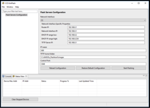
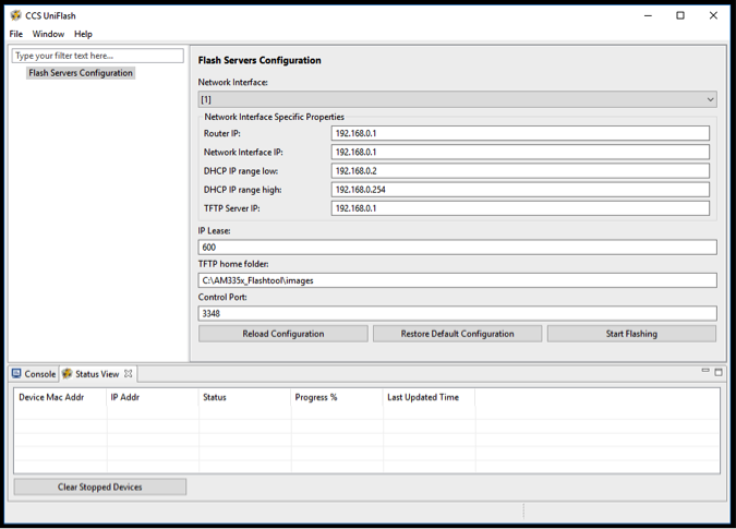
Once the UniFlash tool is installed, you will need to modify the configuration files so that the tool uses more appropriate IP addresses. By default, the configuration files use the 192.168.100 subnet. However, the USB RNDIS connection on the example system was configured to use the 192.168.0 subnet. Therefore, the following configuration files need to be modified:
File uniflash_3.4/third_party/sitara/opendhcp.ini:
- Line 22:
- Original version:
- 168.100.1
- New version:
- 168.0.1
- Original version:
- Lines 117 – 119:
- Original version:
- DHCPRange=192.168.100.2-192.168.100.254
- NextServer=192.168.100.1
- Router=192.168.100.1
- New version:
- DHCPRange=192.168.0.2-192.168.0.254
- NextServer=192.168.0.1
- Router=192.168.0.1
- Original version:
File uniflash_3.4/third_party/sitara/opentftp.ini:
- Line 23:
- Original version
- 168.100.1
- New version
- 168.0.1
- Original version
Depending on your USB RNDIS connection configuration, you should adjust the default subnet accordingly. If you do not wish to modify the configuration files, you can always manually modify the subnet values when running the tool.
6.2.2 Compiling the Binary
Next, you will need to modify the hsi2c_eeprom example in order to create a program that will program a custom value into the EEPROM to set the board ID. As part of the installation instruction for the GCC cross compiler, you should have set the LIB_PATH environment variable. This variable must be set for the makefiles for the GCC build to work correctly.
- Replace the c file with the one provided (see Appendix A: hsi2cEeprom.c)
- Change directories to: AM335X_StarterWare_02_00_01_01/examples/beaglebone/hsi2c_eeprom
- Replace the contents of c with the provided code. This code uses a polling I2C method to read values from and write values to the EEPROM.
- Modify the c file with your appropriate board ID value
- On approximately line 85, there are two #define variables that tell the program the number of bytes to write the EEPROM (NUM_BYTES_TO_WRITE) as well as the values to write to the EEPROM (EEPROM_VALUE_TO_WRITE).
- Currently, these values are set to the OSD3358-SM-RED board ID. These values should be updated to program your board ID.
- Replace the hsi2c_eeprom linker command file with the one provided(See Appendix B: hsi2cEeprom.lds):
- Change directories to: AM335X_StarterWare_02_00_01_01/build/armv7a/gcc/am335x/beaglebone/hsi2c_eeprom
- Replace the contents of the linker command file, lds, with the provided code. This will place the program within the internal AM335x memory so that it can be used directly as a Secondary Program Loader (SPL) without having to initialize DDR.
- Build the program
- In the same directory as the linker command file: AM335X_StarterWare_02_00_01_01/build/armv7a/gcc/am335x/beaglebone/hsi2c_eeprom
- Execute the following commands:
- make clean
- makeCaveatCompiling the binary on Widows (using Cygwin)
Generally, Starterware can build output files in 2 versions: “Debug” and “Release”. From the Windows command line (this example uses Cygwin), this version of Starterware will only build the “Debug” version of the output. Therefore, the compiler will look for any necessary library files under the “Debug” folder of the library. Unfortunately, the libraries for “drivers“, “system_config” and “platform” do not have a “Debug” folder for the default StarterWare installation for Windows. To overcome this issue:
Go to the following directories, all under your install directory; make a “Debug” directory; and manually copy the library binaries from the “Release” directory into the “Debug” directory:- …AM335X_StarterWare_02_00_01_01binaryarmv7agccam335xbeagleboneplatform
- …AM335X_StarterWare_02_00_01_01binaryarmv7agccam335xdrivers
- …AM335X_StarterWare_02_00_01_01binaryarmv7agccam335xsystem_config
Additionally, if you receive error messages like: “cannot find -lc” or “cannot find -lgcc”, make sure library path environment variable, LIB_PATH, is set properly. You can verify if “gcc” is working properly by running the command “gcc -v” on the command line.
- Collect the compiled binary to program into the device
- Change directories to: AM335X_StarterWare_02_00_01_01/binary/armv7a/gcc/am335x/beaglebone/hsi2c_eeprom/Debug
- Collect the following file to be used to program the device: bin
If you need to change the value programmed into the EEPROM for the board ID, you can update the hsi2cEeprom.c file from Step 2 and then recompile the executable using Step 4.
6.2.3 Programming the Device
Now that you have the executable program, hsi2cEeprom.bin, that will program the board ID into the EEPROM, you need to use the UniFlash tool to load and run the program.
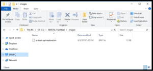
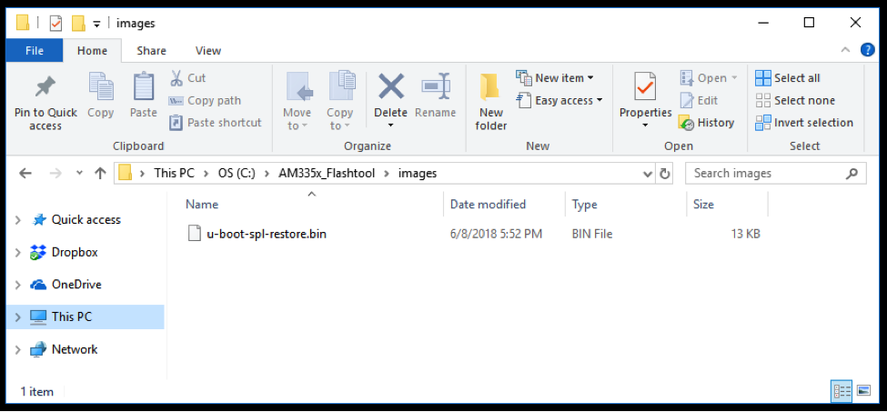
- Update the UniFlash file to load into the device
- Open folder: C:AM335x_Flashtoolimages
- Copy bin to this directory
- Change the name of the file to u-boot-spl-restore.bin

- Setup the UniFlash tool
- Open the UniFlash tool
- Select “New Target Configuration”
- Select “Sitara Flash Connections” for “Conection”
- Select “Sitara Flash Devices” for “Board or Device”
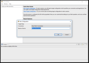

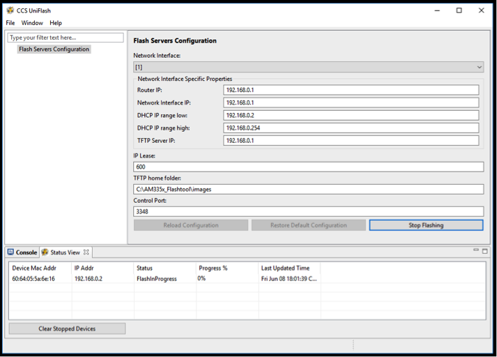
- At this point, you should see the following settings in the tool (These can be adjusted if they are not correct for your setup).

- Optional: View program output
- Connection UART-to-USB adapter to the UART0 interface of the target system
- Start a terminal emulator program (such as Putty)This will allow you to see the output of the program on UART0 but is optional.This will allow you to see the output of the program on UART0 but is optional.
- Load and execute the program
- Connect a USB cable from the appropriate USB interface of the target system to the host system that is running CCS UniFlash.
- Boot the board in the appropriate boot mode
- Note: In Windows, you should hear a notification that the target system has connected to the host using USB RNDIS. You should also be able to see this connection in the “Network Connections” window. By looking at this connection, you can debug any IP address issues you may have with the UniFlash IP settings.
- Click the “Start Flashing” button in UniFlash
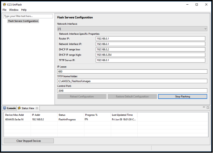
- After a few seconds (up to a minute), you should see the target system populate a line in the “Status View”. This will always show a “Progress %” of “0%” even though the program has been loaded and executed by the target system. You can view the download of the executable with a tool such as WireShark3.
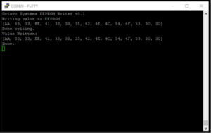
- If you have the optional program output enabled, then you should see the following output on the UART0 interface (with the value that you set in the program instead of the default value pictured below).

- Close UniFlash since the target system has been successfully programmed.


7 References for OSD335x EEPROM During Boot
For more information on software and optional tools, please refer to the following links:
- U-Boot https://github.com/u-boot/u-boot
- Putty https://www.putty.org/
- WireShark https://www.wireshark.org/
8 Appendix A: hsi2cEeprom.c
The code files associated with this App Note can be found here.
9 Appendix B: hsi2cEeprom.lds
The code files associated with this App Note can be found here.
Please contact us on the forums for assistance https://octavosystems.com/forums/
*****
