OSD335x Bare Minimum Board Boot Process
Published On: August, 4, 2017 By: Eshtaartha Basu | Updated: February 6, 2019 by Cathleen Wicks
Introduction
This document will take you through the bring-up process of the Printed Circuit Board (PCB) developed as part of the OSD335x Reference Design Lesson 1.
We begin with bringing-up the newly manufactured board (PCB) to make sure it is functional. Then we set up the necessary software environment including the TI Code Composer Studio (CCS) IDE and Starterware. We conclude with the demo apps to verify the overall functionality of the board.
Prerequisite
This article is a part of the broader OSD335x Reference Design Lesson 1 series which consists of a sequence of articles designed to help you build the bare minimum circuitry required to boot the OSD335x.
We recommend reading the article OSD335x Peripheral Circuitry before this one. This article builds upon the foundation outlined in it.
Before continuing with the article, it is assumed that you have read and implemented all the steps given under Power circuitry, Reset circuitry, Clock circuitry and Peripheral circuitry articles of the OSD335x Reference Design Lesson 1 and your board is already manufactured and with you.
All design files for this lesson can be downloaded here.
This article as well as the entire OSD335x Design Tutorial can be downloaded here.
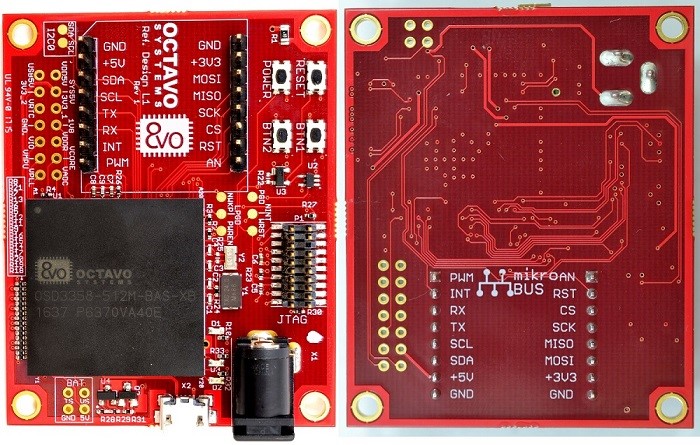
The Board (PCB)
The board built as part of previous articles of this lesson should look similar to Figure 1 (Assuming you chose Red color for solder mask and white color for silk screen).
Basic board bring-up
This section describes the various tests that need to be done during the board bring-up process.
Tests before board power-up
The newly manufactured PCB should be examined before powering it up for the first time to prevent damage to the board.
- Use a Digital Multi Meter (DMM) to make sure there are no shorts (resistance <= 100ohms) between:
- Power input pins and ground.
- Power output pins and ground.
- Between power inputs and power outputs – This is where all the test points can be very helpful.
- If there are any shorts, try to locate the source of the short. This can be done by:
- Examining schematics and layout.
- In many cases, the only way to isolate shorts is to remove components connected to the short one by one until the short is resolved.
- Once you have discovered the source of the problem, you can try to modify the board to fix the issue. This can involve cutting traces or re-wiring components. Unfortunately, sometimes boards cannot be fixed and the design must be re-spun (i.e., schematics and layout updated and boards re-manufactured). If you have to re-spin a board, please make sure to update the revision code on the board.
- Use a DMM to check the resistance between:
- All power inputs, power outputs and ground.
- Between power planes and ground.
- In any case, if the resistance is less than 100ohms, you need to be very careful during power-up to make sure no components have issues.
- Check if the correct components are used by reading the marking on the devices.
- Check if the orientations of the components are correct.
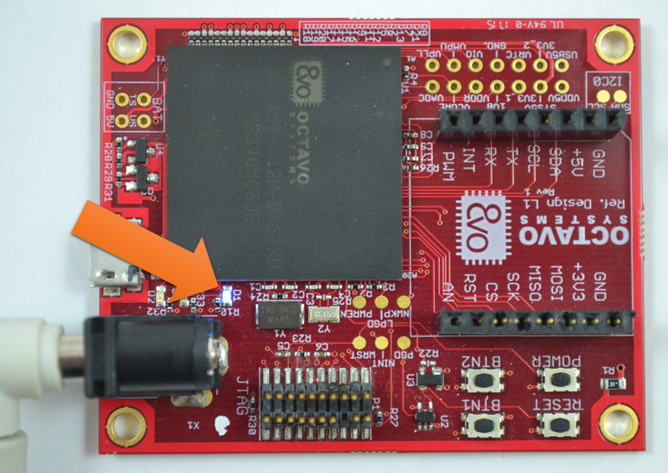
After performing all the above tests, we can power up the board using the DC barrel jack. If everything goes well, you should see the power LED PWR light up as shown in Figure 2.


Possible problems after board power-up
Once the board is powered up, if you observe sparking, overheating or smoke from any of the components, TURN OFF POWER TO THE BOARD IMMEDIATELY to avoid further damage to the board and prevent a possible fire hazard. For any component that failed, please make sure:
- The symbol pinout of the component in schematic matches with its datasheet pinout. – Please make sure that you have the latest version of the datasheet since documentation can be updated / corrected between the time of symbol creation and board manufacture.
- The footprint of the component on PCB matches with the footprint specified on its datasheet.
- The symbol to footprint pin mapping is correct.
- All the components are supplying power within their specified output current limits. For example, if you notice that the voltage of one of the power outputs of the SiP, let’s say, SYS_VDD1_3P3V, is low (less than 3.3V), there is a possibility that too much current is being drawn from it. Make sure the current output of SYS_VDD1_3P3V is within its maximum value to restore its output voltage to 3.3V.
- If possible, try to solve the problem by manually cutting suitable traces on the PCB/making connections using a thin wire. If the problem cannot be solved using these methods, you will have to re-spin the board.
Tests after power-up
If the power LED is lit and you don’t observe any smoke, sparking or heating issues then we can consider it a successful power-up. But, this does not mean the board is fully functional. We can test for functionality by running demo apps. However, before running the demo apps we need to make sure the board is in the state we expect it to be in. To do this we need to:
- Check the following voltage levels (with tolerance of +/- 5%) using the available test points/pads:
- Verify if VIN_AC is at 5V (assuming you’re using DC barrel connector for power input).
- Verify if SYS_VOUT is at 5V (assuming you’re using a 5V power input).
- Verify if SYS_VDD1_3P3V is at 3.3V.
- Verify if SYS_RTC_1P8V is at 1.8V.
- Verify if the test pad PGD (PMIC_OUT_PGOOD) is at 1.8V and WRST (WARMRSTN) is at 3.3V to make sure the OSD335x is not being held in reset.
If any of the above voltages are not at the desired level, please use the test points/test pads with an oscilloscope and DMM to find out which component(s) is responsible for the erroneous voltage. One thing to be aware of is that the voltage on a power rail or signal pin can drop if the load is trying to draw more current than the source can provide.
If you’ve made it this far through the article and if everything looks good on your board, pat yourself on the back. Good job! Now you’re ready to run some code!
Setting up software environment (for Windows 7,8 and 10 OS)
Installing Code Composer Studio
For our design, we will use the Code Composer Studio(CCS) Integrated Development Environment(IDE) to compile, debug and load programs to the OSD335x. The OSD335x uses the AM335x processor from Texas Instruments (TI). Therefore, for the AM335x, we will use the IDE developed and supported by TI. You can use third party IDEs and compilers if necessary.
Steps to install Code Composer Studio:
- You can download the CCS 7.2.0.00013 (which was the latest version at the time of writing this article) installer from this page. The below mentioned steps are for the offline installer. All the demo apps have been tested on CCS 7.2.0.00013 and CCS 6.2.0.00050. You may use CCS 6.2.0.00050 if you face compatibility issues with CCS 7.2.0.00013.
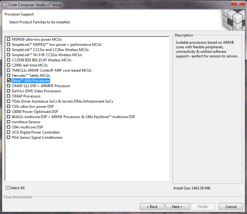
- Midway through the installation process, the installer will ask you to Select Product Families to be installed. Choose Sitara as shown in Figure 3 and click next (if you plan to use CCS for other TI processors, you should select to install those now; else you will have to completely re-install CCS if you need to add support for other processors).
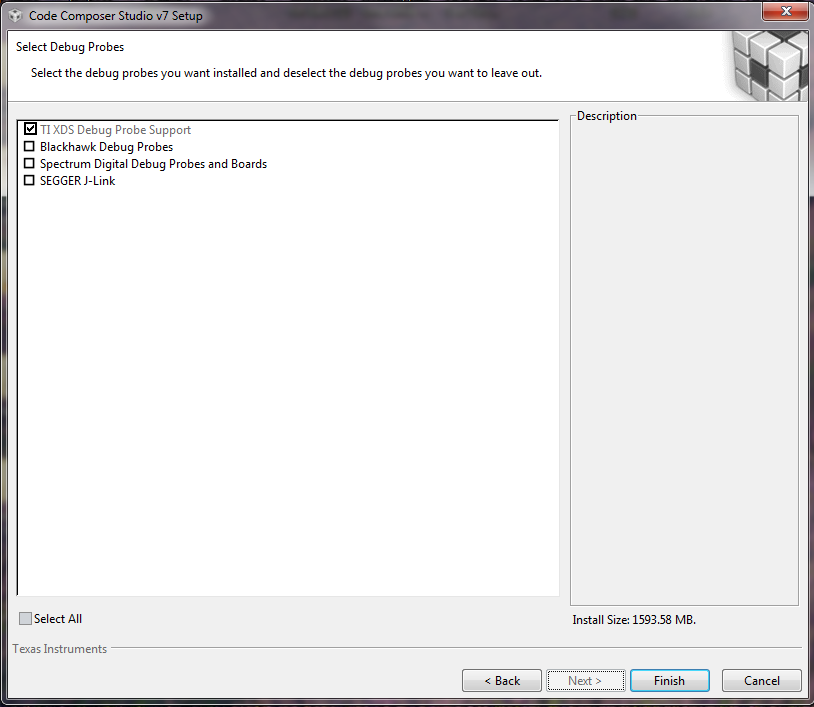
- We are using XDS110 debug probe. Therefore, we will choose XDS under debug probes, as shown in Figure 4 and hit next. If you are using a different debugger, please select and install those instead. Follow the onscreen instructions to complete the installation.
Installing StarterWare
StarterWare is a free software development package that provides bare metal (non-OS) platform support for TI ARM and DSP processors. StarterWare includes Device Abstraction Layer (DAL) libraries and example applications that demonstrate the capabilities of the peripherals on the TI processors. StarterWare also provides pre-built binaries for quick evaluations on the target. To keep things simple and to avoid using an OS like Linux, we will be using Starterware platform for this lesson. Linux will be introduced in the next lesson.
To install StarterWare:
- Go to http://processors.wiki.ti.com/index.php/StarterWare.
- Download StarterWare 02.00.01.01 for the AM335x (TI Account Login required. You can download the software only if TI approves it).
- Install StarterWare 02.00.01.01 using on screen instructions.
Debugger
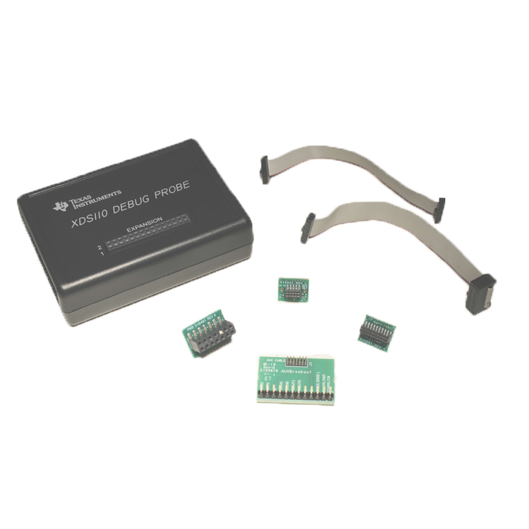
To load the program to the OSD335x, we need a debugger. We have tested the Demo Apps using XDS110 from Spectrum Digital (shown in Figure 5). You are free to use other debuggers if you have them. We have only validated operation on the XDS110 which you can get here.
Demo Apps
Demo App 1: LED Dimmer
The objective of this app is to demonstrate the use of the GPIO and EHRPWM peripherals within the OSD335x.
Demo App 1 generates a hardware PWM signal on the EHRPWM1A (GPIO1_18) pin which is connected to LED D2 on the board and a software PWM signal on the GPIO1_15 pin which is connected to LED D3 on the board. The brightness of each of these LEDs will be controlled by their respective PWM duty cycles and will be set to the maximum value (i.e., always on) in the beginning.
The duty cycle of the hardware PWM signal for LED D2 will be controlled by button BTN1. When the button is first pressed and held, the duty cycle will slowly decrease, which will cause the LED to dim. This will continue until the minimum duty cycle is reached, and the LED will turn off. If you continue to press the button, the duty cycle will then increase, which will cause the LED to brighten back up to the maximum duty cycle. This process repeats itself as long as BTN1 is pressed. The duty cycle of the software PWM signal for LED D3 will be controlled by button BTN2. The behavior of the PWM duty cycle controlled by BTN 2 is same as that of BTN1.
All the CCS design files required for Demo App 1 and Demo App 2 can be found here.
Running Demo App 1
- Open CCS.
- Create a new CCS Project (In Project Explorer, right click > New > CCS Project)
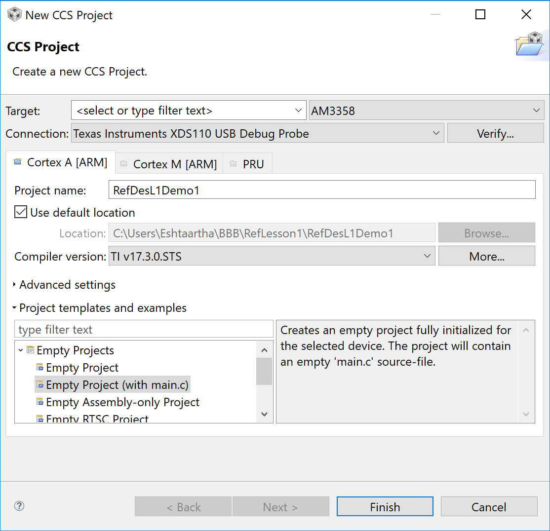
- Name the project as RefDesL1Demo1. Configure the project as shown in Figure 6 and hit Finish.
- Target: AM3358.
- Connection: Texas Instruments XDS110 USB Debug probe.
- Compiler version: TI v16.9.3.LTS or higher.
- Project template: Empty Project (with main.c).
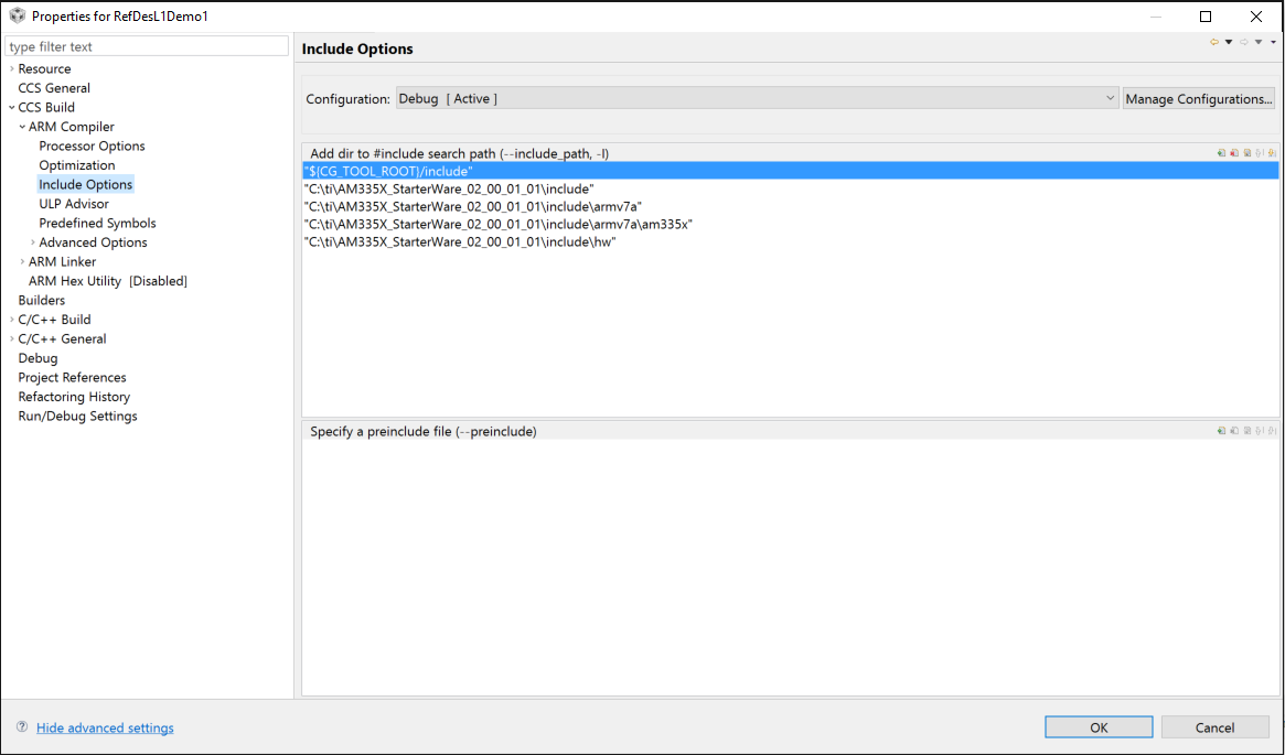
- The compiler will need access to many different Starterware folders and libraries in order to compile our code. Add the following paths to the ARM Compiler’s Include Options as shown in Figure 7 (To find Compiler Include Options, right click on Project Name in Project Explorer > Properties > CCS Build > ARM Compiler > Include Options. The below paths are given assuming you have installed Starterware at C:ti. If not, alter the paths suitably):
- C:tiAM335X_StarterWare_02_00_01_01include
- C:tiAM335X_StarterWare_02_00_01_01includearmv7a
- C:tiAM335X_StarterWare_02_00_01_01includearmv7aam335x
- C:tiAM335X_StarterWare_02_00_01_01includehw
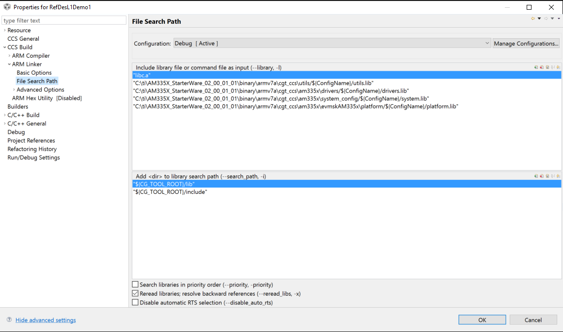
- The linker will need access to many different Starterware folders and libraries in order to compile our code. Add the following paths to the ARM Linker’s File Search Path as shown in Figure 8 (To find Linker File Search Path, right click on Project Name in Project Explorer > Properties > CCS Build > ARM Linker > File Search Path. The below paths are given assuming you have installed Starterware at C:ti. If not, alter the paths suitably):
- C:tiAM335X_StarterWare_02_00_01_01binaryarmv7acgt_ccsutils/${ConfigName}utils.lib
- C:tiAM335X_StarterWare_02_00_01_01binaryarmv7acgt_ccsam335xdrivers/${ConfigName}drivers.lib
- C:tiAM335X_StarterWare_02_00_01_01binaryarmv7acgt_ccsam335xsystem_config/${ConfigName}system.lib
- C:tiAM335X_StarterWare_02_00_01_01binaryarmv7acgt_ccsam335xevmskAM335xplatform/${ConfigName}platform.lib
- Delete main.c from your project and replace it with RefDesL1Demo1.c (provided as part of CCS design files. Link given above).
- The default linker command file, AM335x.cmd and the given startup code file, init.asm that CCS provides are not suitable for our demo apps because of the following reasons:
- The default linker command file uses the default startup code which sets the processor to User Mode before calling the main() function. But, the processor needs to be in Privilege Mode/System Mode to be able to write to GPIO control module registers for the GPIO or EHRPWM registers as part of our demo projects.
- The given startup code file, init.asm, is configured to operate using external DDR3 with 4KB of stack assigned for interrupt requests. While the DDR3 memory exists in the OSD335x, we do not have the DDR initialization code in the demo program and therefore need to run the program using only the AM335x internal memory. Given that we are using internal memory, we will have to reduce interrupt request stack size to 256B.
- To solve the above problems, Octavo Systems provides two files: AM335x.cmd and init.asm, which make CCS use custom startup code before calling main() function. The custom startup code sets the processor to System Mode before calling main() function. It also reduces the interrupt request stack size to 256B.
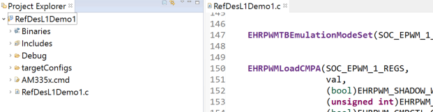
- Replace the default AM335x.cmd file under your project files with the modified AM335x.cmd file (provided as part of CCS design files. Link given above) as shown in Figure 9. Make sure you keep a backup of the original AM335x.cmd file in case you want to restore starterware to its original form for other future applications.
- Import system_config project from (folder path is given assuming you have installed Starterware at C:ti, otherwise adjust the path accordingly): C:tiAM335X_StarterWare_02_00_01_01buildarmv7acgt_ccsam335x. Replace the default init.asm file under this project with the modified init.asm file (provided as part of CCS design files. Link given above) as shown in Figure 10. Make sure you keep a backup of the original init.asm file in case you want to restore starterware to its original form for other future applications.
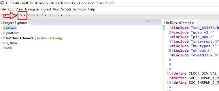
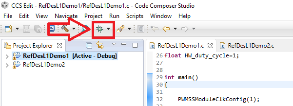
- Build the project using the build button as shown in Figure 11.
- Before we can run the demo app, we need to build 3 libraries: utils.lib, drivers.lib, and platform.lib. We will be using many APIs from these libraries in our demo apps. To build the libraries, you need to (folder paths are given assuming you have installed Starterware at C:ti, otherwise adjust the path accordingly):
- Import utils project from C:tiAM335X_StarterWare_02_00_01_01buildarmv7acgt_ccs
- Import platform project from C:tiAM335X_StarterWare_02_00_01_01buildarmv7acgt_ccsam335xevmskAM335x
- Import drivers project from C:tiAM335X_StarterWare_02_00_01_01buildarmv7acgt_ccsam335x.
- Build each of the above projects by selecting the project and hitting the build button as shown in Figure 11.
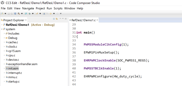
- Now we are ready to build Demo App 1. Select RefDesL1Demo1 project and build it. If you have followed all the instructions given above, it should build without errors.
- Connect the debugger to your computer.
- Connect the 20 pin JTAG connector of the debugger to the JTAG header on the board. Make sure the board is powered ON.
- On power-up, the AM335x processor will look for valid boot images during the boot sequence (SPI0 -> MMC0 -> USB0 -> UART0 in case of OSD335x Bare Minimum Board). Since OSD335x Bare Minimum Board has no boot image on any of its interfaces, the AM335x processor will continue to look for an image. At this point, JTAG will be able to take control of the processor and allow the software to be loaded through the JTAG debugger and CCS.
(If you are trying this step on OSD3358-SM-RED board instead of OSD335x Bare Minimum Board, then, make sure the SD card slot is empty and hold the SD boot button (S3) before applying power to the RED board to make sure AM335x cannot find a valid boot image during boot sequence. This is essential to allow JTAG debugger to take control of the AM335x processor and be able to load programs through CCS).
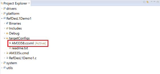
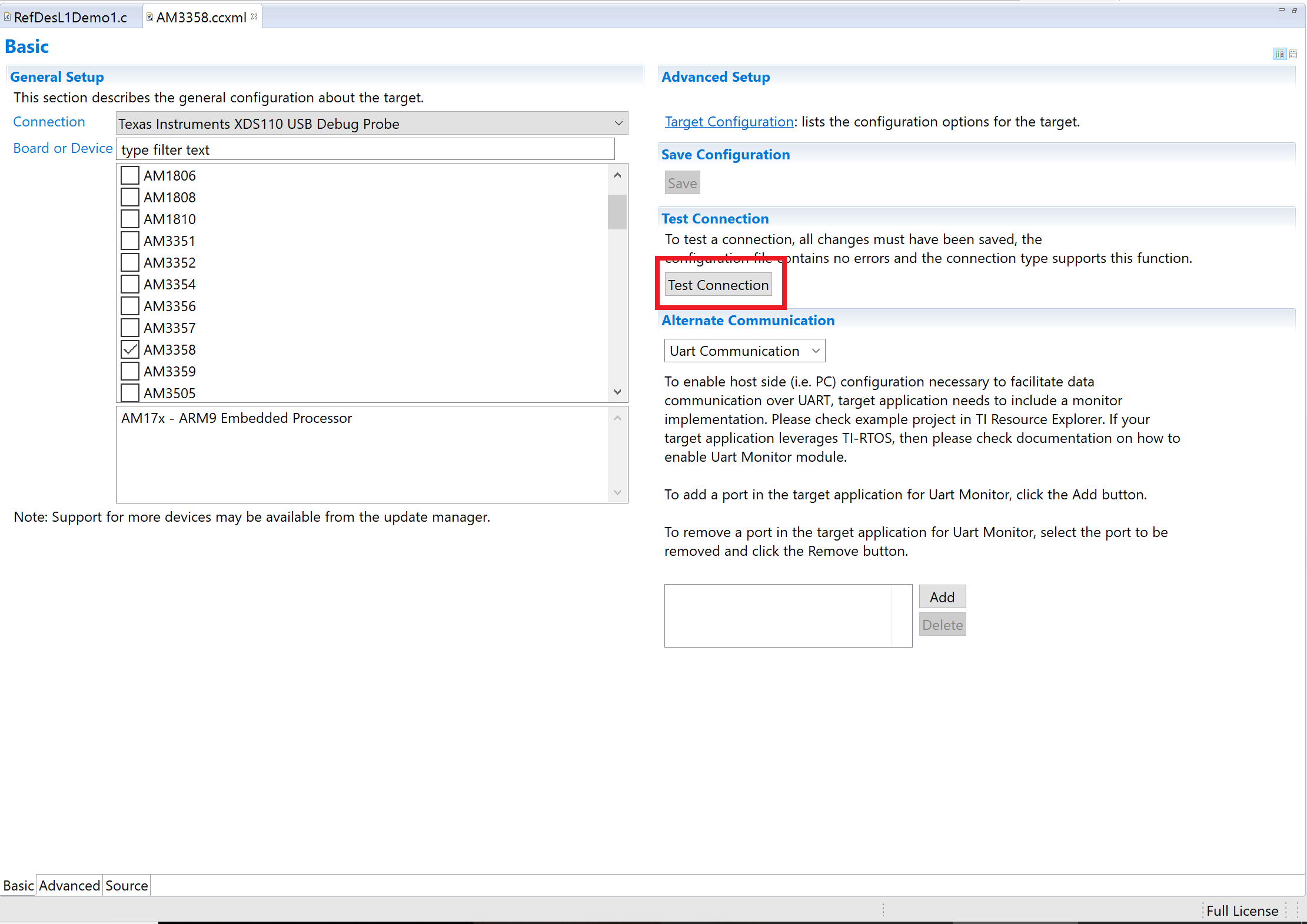
- In the drop down menu of your project folder, open targetConfigs drop down menu and then open AM3358.ccxml file as shown below.
- Click on Test Connection button to test the JTAG connectivity as shown below. CCS will perform a series of tests and you should receive the JTAG DR Integrity scan-test has succeeded message or something similar at the end of the testing process. You can use the TI’s Debugging JTAG Connectivity Problems wiki page to resolve any errors, if any. Probe the clock signals and use an oscilloscope to make sure OSC0 is operating at 24MHz and OSC1 is operating at 32.768KHz if JTAG connectivity test fails repeatedly.
- You can continue with Demo App debug process once the JTAG connection is successfully verified.
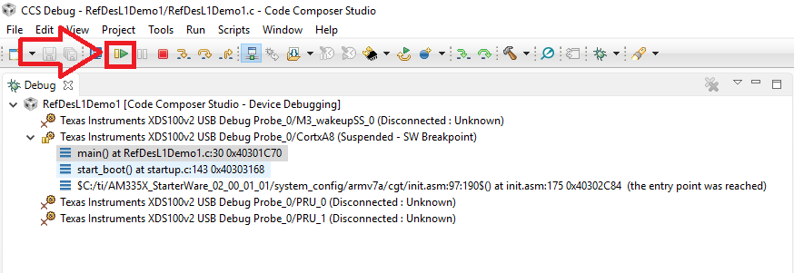
- Press the Debug button as shown in Figure 12.
- Once the program gets loaded, you should see the below screen (Figure 13). Hit the Resume button to run the program on the board.
- Verify the functionality of Demo app 1 by pressing the user buttons BTN1 and BTN2 and observing the brightness of user LEDs D2 and D3 as shown in Figure 14.

Figure 14 Demo App 1 in action
Demo App 2: Motion Detector (Link to download CCS design files given above)
The objective of this app is to demonstrate the use of peripheral header with the OSD335x.
This project uses the MOTION click board (https://shop.mikroe.com/click/sensors/motion). It can be directly plugged into the peripheral header. The MOTION click board detects motion of living bodies. It picks up the IR radiation emitted by living bodies using its PIR sensor. Whenever a motion is detected, it sends an interrupt to the OSD335x using the INT pin of peripheral header. The OSD335x detects this interrupt and alternatively blinks LED D2 and LED D3 to indicate motion detection.
Running Demo App 2
The procedure to run demo app 2 is exactly same as that of demo app 1 except that you have to use RefDesL1Demo2.c (provided as part of CCS design files. Link given above) instead of RefDesL1Demo1.c. Figure 15 shows Demo App 2 in action.
| << Return to “OSD335x Peripheral Circuitry” | Continue to “OSD335x Lesson 2: Introduction to Bare Minimum Circuitry for Linux Boot ” > |
