


OSD335x System-in-Package
A New Era of Integration and Flexibility based on AM335x
Additional Variants:
- OSD335x-SM – Same functionality in a smaller package and adds EEPROM.
- OSD335x C-SiP – Same functionality but adds eMMC Flash, MEMs Oscillator, and EEPROM.
Faster and Smaller Designs, Simplified Supply Chain, Low Cost Manufacturing
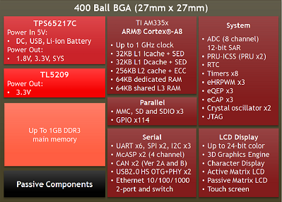
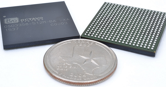
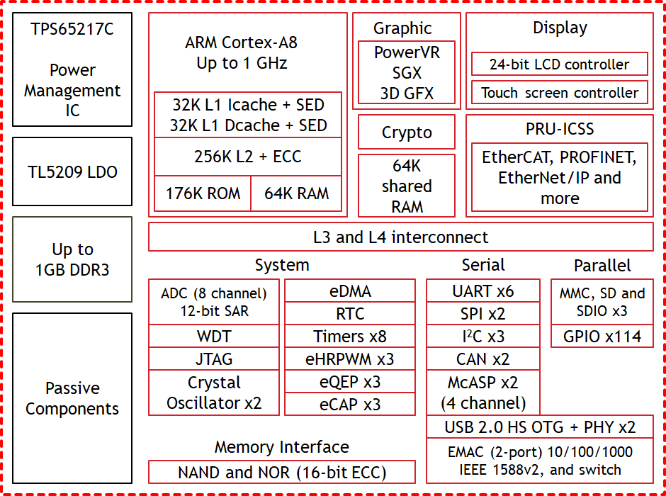
The Octavo Systems OSD335x System-in-Package (SiP) device is the first device in the OSD335x Family. It integrates the Texas Instruments Sitara ARM® Cortex®-A8 AM335x Processor, DDR3 memory, TPS65217C PMIC, TL5209 LDO, and all needed passive components into a single 27mm X 27mm BGA package.
Integrating the DDR3, power system, and passive devices into the single package removes the complexities of DDR3 to processor interfacing and power sequencing. This allows for a vastly simplified final system design.
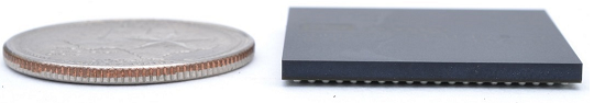
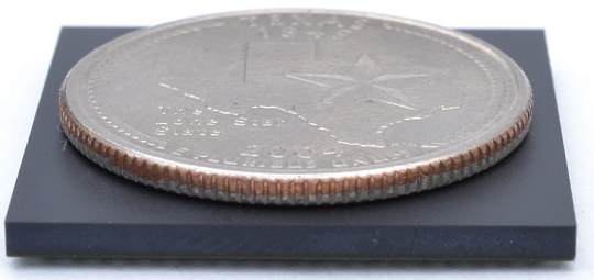
The 400 Ball BGA package is 40% smaller than the equivalent discrete design making it a great solution for space constrained applications. The package also utilizes a 1.27mm (50 mil) ball pitch making it extremely easy to assemble. The ball pitch also allows for the use of more relaxed Printed Circuit Board (PCB) design rules, saving PCB cost.
The OSD335x provides a quick and easy way to implement a system around the TI AM335x while also providing space savings, simplified supply chains, lower cost manufacturing, and greater reliability.

|
|
- OSD335x BAS/IND to OSD335x-SM Migration Guide – Detailed guide to help migrate a a OSD335x-BAS/IND design to the smaller, easier to use OSD335x-SM
- OSD335x Schematic Checklist – Detailed Technical Checklist to Help Users Review OSD335x-BAS/IND or OSD335x-BSM/ISM designs
- OSD335x-BAS/IND Power Application Note – Application Note Explaining the Power Management System of the OSD335x
- OSD335x Reference Design Tutorial Series – A series of articles walking through all of the information needed to design with the OSD335x.
- AM335x Pins Mapped to OSD335x Pins – A set of tables that outlines how the AM335x pins map to the pins on the OSD335x.
- OS335x-BAS/IND Thermal Management – An Application Note outlining the Thermal Performance and Key Thermal Parameters of the OSD335x.
- OSD335x EEPROM During Boot – Techniques to program an EEPROM with a unique code, a board ID, to configure your Linux image during boot.
| Product Number | Description | Price | Order From |
|---|---|---|---|
| OSD3358-512M-BAS | System-In-Package - AM3358, 512MB DDR3L, TPS65217C, TL5209, Passives - 27mm X 27mm, 400 Ball BGA, 0°C to 85°C | Contact Sales | Digi-Key Mouser Arrow Avnet Request a Quote |
| OSD3358-512M-IND | System-In-Package - AM3358, 512MB DDR3L, TPS65217C, TL5209, Passives - 27mm X 27mm, 400 Ball BGA, -40°C to 85°C | Contact Sales | Digi-Key Mouser Arrow Avnet Request a Quote |
Development Boards
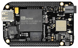 The BeagleBone™ Black Wireless is one of the quickest ways to get up and running with the OSD3358. This low cost board from BeagleBoard.org features the OSD3358-512M-BAS as well as 802.11 b/g/n and Bluetooth v4.1. It is also compatible with all BeagleBone™ Black expansion capes. The BeagleBone™ Black Wireless is completely open-source and is supported by the large and active BeagleBoard.org® community.
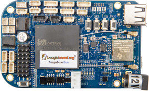
The BeagleBone® Blue is reference platform designed by BeagleBoard.org® as a robotics platform. It features the OSD3358-512M-BAS, 802.11 b/g/n and Bluetooth v4.1, 4 quadrature encoders, 4 DC motor drives, 8 servo outputs, as well as a 9 axis IMU and barometer. It is a great platform to prototype robotics or motor control applications. The BeagleBone® Blue is completely opensource and is supported by the large and active BeagleBoard.org® community.
Symbols
To help make designing with the OSD335x devices easier a number of schematic symbols have been provided below. They are for multiple schematic capture programs and multiple configurations. Please choose the one that best suits your needs.
Software
Provided below is a copy of the DDR3 calibration program that is provided from Texas Instruments. It has been provided here for your convenience.
In order to help get you started using the OSD335x we, in partnership with BeagleBoard.org, have created a reference design around the OSD3358-512M-BAS. The reference design is a Single Board Computer that is compatible with BeagleBone Black ecosystem. This reference design will run the BeagleBone Linux distributions and is also compatible with all capes. If copied exactly, it will perform like a BeagleBone Black. This is a reference design only. The boards are not available to purchase.
Note: This is reference design replaced the original OSD3358 SBC Reference Design that was done in Orcad. This design represents the current best practices for designing with the OSD335x. If you are interested in the legacy design, it can be found here.
FAQs
In our lab, we have used both the XDS110 and XDS200 emulators. Depending on your emulation / debug needs, you can also use higher end emulators like the XDS560v2.
If you plan to use debug features like trace that are available on higher end emulators, please make sure that you bring the EMU2/EMU3/EMU4 pins to the JTAG header. If you do not plan to use those higher end debug features, then those particular EMU signals do not need to be routed to the JTAG header.
Texas Instruments also provides a number of different websites detailing information about the emulators that can be use with the AM335x processor, and thus the OSD335x SiP, as well as general inofrmaton about JTAG connectors and adapters:
direct linkLinux images from Bealgeboard.org require EEPROM to be programmed with a board ID. The following solutions can be used to overcome this issue:
1. Bypass the checks in the bootloader (u-boot)
2. Use Robert Nelson’s patch to create u-boot that will boot and allow you to program the EEPROM: In u-boot apply the patch:
u-boot also uses a device tree that you might need to modify. You should find the u-boot device tress in ./arch/arm/dts It is useful to look through the 0001-am335x_evm-uEnv.txt-bootz-n-fixes.patch patch from Robert Nelson (see https://eewiki.net/display/linuxonarm/BeagleBone+Black) since this patch modifies device trees and can point you to important directories in u-boot.
A more detailed explanation of the above options can be found in this forum post.
direct link
Generally, XDS200 connectivity issues can be resolved by updating its firmware.
To update a XDS200-class JTAG debugger connected via USB, using a Windows host is highly recommended. Close any instances of CCS that are running in your system. Open a Windows Command Prompt and issue the following commands:
1. Go to the directory where the utility is installed:
- C:\>cd C:\ti\ccsv6\ccs_base\common\uscif\xds2xx
2. Run the configuration just to make sure a XDS200-class debugger is connected and to confirm the firmware revision installed on it:
- C:\ti\ccsv6\ccs_base\common\uscif\xds2xx>xds2xx_conf get xds2xxu 0
3. If you have a single XDS200 connected via USB:
Run the following commands in the exact order shown below (the batch file update_xds2xx does this in reverse order, increasing the chances of failure):
- C:\ti\ccsv6\ccs_base\common\uscif\xds2xx>xds2xx_conf update xds2xxu 0 xds200_firmware_v1008.bin
- C:\ti\ccsv6\ccs_base\common\uscif\xds2xx>xds2xx_conf program xds2xxu 0 xds200_cpld_v1008.xsvf
- C:\ti\ccsv6\ccs_base\common\uscif\xds2xx>xds2xx_conf boot xds2xxu 0
4. After that, run the command in step 2 again to check if the correct firmware was loaded.
- C:\ti\ccsv6\ccs_base\common\uscif\xds2xx>xds2xx_conf get xds2xxu 0
If connectivity issues persist, please go through the XDS200 Wiki to find out more information.
The OSD335x is BeagleBoard Compatible meaning they can run any of the software provided by BeagleBoard.org. Here is a link to getting started on Beaglebone.
The AM335x Software Design Guide from TI will help you become familiar with the overall software design process for AM335x. TI also provides Linux and TI-RTOS support for software development.
direct linkYes, OSD335x family runs all Linux distributions supported by TI for AM335x. It is also officially BeagleBoard Compatible so it will run the same Linux distributions found on Beaglebone Family of products.
direct linkThese power pins are driven by the TPS65217C PMIC and are used internally to power the AM335x, DDR and other components. These pins are all connected within the SiP and should not be connected externally. Optionally, these pins can be brought out as test points for debugging purposes only. They should NEVER be used to power external components.
direct linkThe following table shows the minimum set of signals that need to be connected externally between the processor (AM335x) and PMIC (TPS65217C) to use the OSD335x-BAS/IND devices. It also shows internal pull up resistor values, the voltage rail they are pulled up to and the specific pad that was pulled up.
| OSD335x Pad Name | PAD | OSD335x PAD Name | PAD | Pull Up Resistor Value | Pull Up Voltage | Pull Up on PAD |
|---|---|---|---|---|---|---|
| PMIC_IN_I2C_SCL | C20 | I2C0_SCL | C16 | 4.7 K | VDDSHV_3P3V | C20 |
| PMIC_IN_I2C_SDA | C19 | I2C0_SDA | C17 | 4.7 K | VDDSHV_3P3V | C19 |
| PMIC_IN_PWR_EN | D19 | PMIC_POWER_EN | C6 | 10 K | SYS_RTC_1P8V | D19 |
| PMIC_OUT_PGOOD | A20 | PWRONRSTN | B15 | NONE | N/A | N/A |
| PMIC_OUT_LDO_PGOOD | B20 | RTC_PWRONRSTN | B5 | NONE | N/A | N/A |
| PMIC_OUT_NINT | B19 | EXTINTN | B18 | 10 K | VDDSHV_3P3V | B18 |
| PMIC_OUT_NWAKEUP | A19 | EXT_WAKEUP | C5 | 10 K | SYS_RTC_1P8V | C5 |
direct link
Power consumption of OSD335x depends highly on usage scenarios. The OSD335x-BAS/IND Power Application Note and Software Power Management with the OSD335x Family application notes will give you detailed information about OSD335x power consumption in various operating states.
Other helpful resources are:
- AM335x Power Consumption Summary: This wiki page provides current and power measurements for common system application usage scenarios. However, these measurements were made for a presently unsupported version of SDK. Updated power consumption data can be found here.
- Power Estimation Tool: This entails modifying and submitting a spreadsheet specifying processor mode and peripheral usage of AM335x. Login to TI website is required and the results will be emailed to the email address used to login.
