OSD335x Lesson 2: Linux Boot Process with the OSD335x
Published On: May, 15, 2018 By: Eshtaartha Basu | Updated: November 14, 2018 by Cathleen Wicks
1 Linux Boot Process with the OSD335x
1.1 Introduction
Linux is a free and open-source operating system created by Linus Torvalds. Due to its openness, flexibility, and tremendous community support and development, Linux has become the operating system of choice for most embedded systems like industrial control systems, robotics applications and IoT devices. There are many Linux distributions, such as Debian and Ubuntu, that pull together utilities, libraries and application software around the Linux kernel to provide a development and execution environment for custom application software.
This article will focus on understanding the boot process a of a OSD3358-SM-RED Debian Linux image running on OSD335x.
Prerequisite
This article is a part of the broader OSD335x Reference Design Lesson 2 series which consists of a sequence of articles designed to help you build the bare minimum circuitry required to boot Linux on the OSD335x. We recommend reading the article OSD335x Lesson 2: Bringing Up a Custom Bare-Bones Linux PCB before this one. This article builds upon the foundation outlined in it.
All design files for this lesson can be downloaded here.
Table of Contents
1Linux Boot Process with the OSD335x
1.1Introduction
1.2OSD335x Debian Linux Boot Process
1.2.1Stage 1: ROM Bootloader
1.2.2Stage 2: Secondary Program Loader (SPL)
1.2.3Stage 3: U-Boot Bootloader
1.2.4Stage 4: Linux Kernel
1.2.5Boot Process Memory Usage
![]()
![]() A PDF version of this Lesson as well as the entire OSD335x Design Tutorial can be downloaded here.
A PDF version of this Lesson as well as the entire OSD335x Design Tutorial can be downloaded here.
![]()
![]() Down load the OSD3358-SM-RED Debian Linux image.
Down load the OSD3358-SM-RED Debian Linux image.

1.2 OSD335x Debian Linux Boot Process
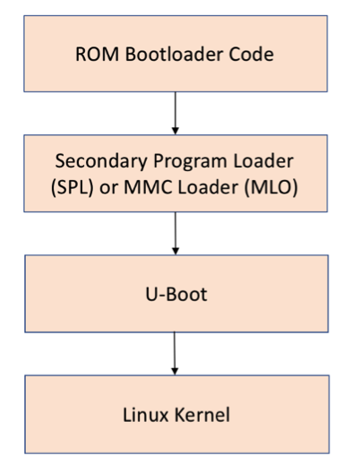
Like many processors, the Texas Instruments AM335x processor inside the OSD335x Family of devices uses a multi-stage boot process to load and run the operating system. This is due to factors such as flexibility in the boot peripherals, boot speed, processor memory limitations, etc. The four boot stages for a standard Linux boot are shown in Figure 1.
1.2.1 Stage 1: ROM Bootloader
The AM335x contains a section of Read-Only Memory (ROM) that implements the first stage bootloader. The ROM Bootloader code is the first piece of code that is executed by the processor when it is released from reset. The ROM is a hard coded piece of software and cannot be changed for a given device but may change between revisions of the processor. The ROM bootloader has the following responsibilities:
- Initial configuration of the device and initialization of boot peripherals
- Memory section setup (stack, heap, etc.)
- Configuration of Watchdog Timer 1 (set to three minutes)
- Configuration of PLL and System Clocks
- Load and begin execution of the next stage bootloader
- Check boot peripherals for next stage bootloader (SPL/MLO)
- Load bootloader from peripheral into the internal RAM of the AM335x and begin execution of the code
The AM335x defines sixteen (16) boot configuration pins (SYSBOOT[15:0]) that are set by the hardware design to inform the bootloaders about hardware system parameters. These parameters include input clock frequency, Ethernet or flash memory configuration (if applicable), output clock configuration, and boot sequence. The ROM bootloader uses the boot sequence parameter to search a given set of boot peripherals for the next stage bootloader. The value of the SYSBOOT pins can be read by the processor via the control_status register (address 0x44E1_0040).
For example, in the Lesson 2 design, by default we set SYSBOOT[15:0] = 0x4018 which sets a boot sequence value of 11000b. From the SYSBOOT Configuration Pins section (Table 26-7) in the AM335x Technical Reference Manual (TRM), this means that the ROM bootloader will search SPI0, MMC0, USB0 and UART0 for the next stage bootloader, in that order. If a properly formatted bootloader is not found, the ROM bootloader will continue to poll the last peripheral, i.e. UART0, until a bootloader is found, or the processor is reset. In the case of UART0, the polling of the bootloader can be recognized by the processor outputting a series of “C” characters on UART0.
It is important to set the boot sequence properly since only the peripherals defined by the boot sequence will be checked by the ROM bootloader for the next stage bootloader. Similarly, it is important to make sure the boot sequence order is correct if multiple peripherals will be used to boot, such as an SD Card and eMMC.
1.2.2 Stage 2: Secondary Program Loader (SPL)
The second stage bootloader is known as the Secondary Program Loader (SPL). Previously, it was also known as the MMC Loader (MLO) but that term has been deprecated but may still appear in documentation. The SPL must operate entirely within the internal memory of the AM335x processor since only the boot peripherals have been initialized by the ROM bootloader. In the case of bare-metal applications that are small enough to fit within the internal memory, the boot process can end at this stage and the application can run. However, this is not the case for Linux.
To boot Linux, one of the most common methods is to use U-Boot (Universal Boot Loader) to perform all of the steps necessary to load and boot the Linux kernel. U-Boot provides a feature rich environment to accomplish its tasks. However, the feature rich U-Boot environment requires more memory than is available in the AM335x internal memory. Therefore, U-Boot is split into a first-stage and second-stage bootloader. The first stage of U-Boot is small and can be used as the SPL for the OSD335x Linux boot process. This split is done automatically during the build process for U-Boot, but the pieces are loaded into separate parts of the boot image.
The main function of the stripped-down SPL version of U-Boot is to perform hardware initialization of the DDR3 memory within the OSD335x, load the larger, fully featured version of U-Boot into DDR memory, and begin execution of that code.
1.2.3 Stage 3: U-Boot Bootloader
The third stage of the OSD335x Linux boot process is the second stage of the U-Boot bootloader. The full-featured version of U-Boot that is being run at this stage is extremely powerful and includes an interactive shell, environment variables, as well as command line utilities to initialize and interact with many different peripherals. These features make U-Boot a very popular bootloader for many embedded devices running Linux.
Once the U-Boot console has been activated, it is possible to stop the automatic boot process via a serial terminal and use the command line interface to interact with the hardware and test its functionality. For example, you are able to interact with I2C or MMC devices to make sure that they are powered and at the correct address. The U-Boot console typically uses the UART0 interface. However, there are interesting projects such as Netconsole that allows the serial terminal to be used over a network interface.
The main function of the U-Boot bootloader is to load and begin execution of the Linux kernel. To do this, it will typically look for a uImage file, which is contains both the Linux kernel and a header that describes the kernel. The uImage file can be found in non-volatile memory attached to the processor, such as an eMMC or a microSD card, or over a network interface via a protocol like TFTP.
The U-Boot environment can be configured by setting environment variables. These environment variables can be 1) configured during the build of U-Boot; 2) set and saved during an interactive U-Boot session; or 3) set or overridden from a file called uEnv.txt which is stored in the /boot directory of the filesystem.
1.2.4 Linux Kernel
In the final stage of boot, the Linux kernel is started which will boot and configure the Linux operating system. During this part of the boot process, all the necessary device drivers are loaded and configured so that the system can operate properly.
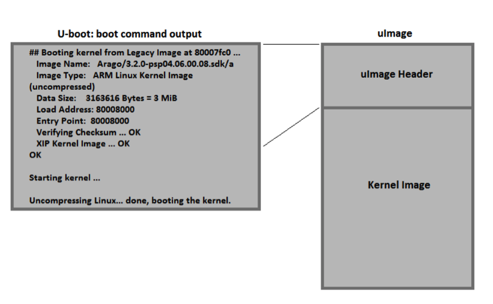
The Linux kernel is wrapped in a header that describes it and the two together create the uImage file that is loaded and executed. The header is 64kB and includes information like the target architecture, the operating system version, kernel size, checksum to verify the kernel image was loaded correctly, etc. When U-Boot loads the uImage, it displays the header information on the serial console as shown in Figure 2.
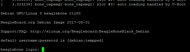
Once the kernel boots, depending on the loglevel and quiet options that are part of the cmdline variable in uEnv.txt, various boot messages will appear on the serial console as drivers and services are loaded. These messages are important debug resources if there are any issues with hardware or software components of the system. Eventually, a login prompt will appear, see Figure X, on the serial console. You can use this to log into the system. This login is important if there are any issues during boot since it allows access to the system when other methods of interacting with the system, such as ssh over a network or a graphical user interface, might not be working properly.
At this point, the Linux operating system has completely booted and you are now able to use it as you would any other Linux operating system to run programs and applications, communicate with system hardware, etc.
1.2.5 Boot Process Memory Usage
While it is important to understand the different stages of the boot process, it is also important to understand where each boot stage lives in memory and the different memory it uses during boot.
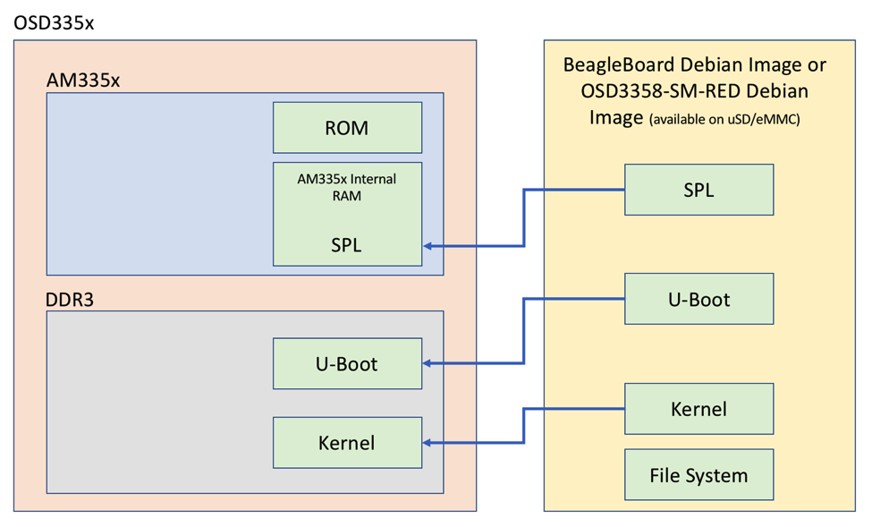
Before the device powers up, the boot code lives in one of two places. First, the ROM Bootloader resides permanently on the AM335x processor and cannot be modified. Second, all other pieces of the boot image (ie the second and third stage bootloaders, and the linux kernel and filesystem) are in non-volatile storage (e.g. a microSD card or eMMC). Once the device powers up, the ROM Bootloader will load the second stage bootloader, i.e. the SPL, into internal AM335x memory. The SPL will load the third stage bootloader, i.e. the full featured version of U-Boot, into the DDR memory that is within the OSD335x device. Finally, the last bootloader stage, i.e. the Linux kernel, will be pulled into the DDR and executed. At that point, the Linux operating system will run using all of the resources of the AM335x and the OSD335x as well as continuing to use the non-volatile storage as the file system. This is shown in Figure 4.
You can download pre-built Debian Linux images that consist of all necessary pieces to boot from BeagleBoard.org or the RED Linux Image Download.
For any questions or concerns, you can reach us at: https://octavosystems.com/forums/
We’d like to thank lewing@isc.tamu.edu and The GIMP for permission to use the ‘Tux’ Linux image used in our social media about this post
*****
| << Return to “OSD335x Lesson 2 Bringing Up a Custom Bare-Bones Linux PCB” | Continue to “OSD335x Lesson 2: Linux Device Tree” >> |
