
Health Monitor Design with OSD335x SiP
Having a full Linux computer, such as the OSD335x System in Package (SiP), the size of a coin enables abundant creativity when designing new IoT applications. The global health sensors market is in the billions and increasing at a rapid rate. When a market changes that quickly, designers need a flexible platform so they can spend time on the features they want to add. They also need reliable, open source hardware and software design tools. Therefore, the OSD335x-SM SiP, the smallest Texas Instruments AM335x module available, gives a solid foundation to build a health monitor.

Get updates to the Health Monitor and all of the IoT Gateway projects
"*" indicates required fields
Easily and Rapidly Prototype a Health Monitor
To get started on a health monitor design, we decided to rapidly prototype with the OSD3358 System-in-Package (SiP) using PocketBeagle® from BeagleBoard.org® and MikroElektronika Click Boards™. The development boards from BeagleBoard.org® are excellent examples of using the OSD335x SiP in a design. BeagleBoard.org® is a customer of Octavo Systems, and is a 501c3 Foundation, focused on education. PocketBeagle® is a completely open source, highly affordable super tiny single board computer featuring the AM335x based OSD335x-SM SiP. PocketBeagle® has header pins that conform to the MikroElektronika mikroBUS™ Click Board™ standard. This is an open standard interface for which over 450 compatible add-on boards provide functionalities that include sensing and communication. Several Click Boards perform various health-monitoring functions such as ECG, EMG, temperature and heart rate. These platforms can be used to prototype many kinds of health monitoring application circuits with minimal effort.
The goal of our health monitor design is to be able to measure the heart rate and clamminess (i.e. temperature and humidity) of an individual using their hands and report the measurements to an IoT gateway server. In order to achieve this, three hardware additions are required for PocketBeagle®
- Heart Rate Click BoardTM
- Temperature and Humidity Click BoardTM
- USB WiFi module
Collecting Heart Rate Data
To monitor heart rate in our health monitor design, we chose the Heart-Rate 3 Click Board. This board features the SFH7050 biomonitoring sensor from OSRAM Opto Semiconductors that has three LEDs and a photodiode for heart-rate monitoring and pulse oximetry measurements. The sensor is able to perform reflective photoplethysmography (PPG), a technique involving measuring changes in light absorption of the skin. The three LEDs emit light of three different wavelengths (Green, Red and IR). The light reflected by the skin is detected by a photodiode. This arrangement forms the optical front end of the heart rate Click Board. The analog signal generated by the photodiode is processed by an Analog front end IC with a high dynamic range.
The analog front end IC, a Texas Instruments AFE4404, features different stages to process the signal and convert it to digital data. This can then be read and interpreted by the microprocessor. The stages involve offset cancellation, amplification, filtering and ADC conversion. Figure 1 shows the block diagram of the heart rate sensing mechanism.

Transmitting Data Easily Over WiFi
In order to make our health monitor design complete, we need to take the data collected and transmit it to the cloud so that it can be recorded and processed into an actionable result. To do this, we can add a USB WiFi module to our design so that the heart rate, temperature, and humidity data can be send to a wireless gateway and sent to the cloud. PocketBeagle® headers expose an additional USB port (i.e. USB1). However, to use this port with a standard USB WiFi adapter, we need to do a few things.
First, we need to enable the USB1 port and make the USB1 port into a “Host” USB port. We can accomplish this by soldering together.
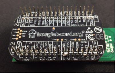
In Figure 2, we can see that to enable the USB1 peripheral, we need to connect the “VI” pin (VIN) to the “VB” (VBUS) pin. Additionally, to set the USB port to “Host” mode, we need to connect the “ID” pin to ground (GND). We can do this by using solder jumpers on the backside of PocketBeagle®. Now that we have enabled the USB1 Host port, we need to connect it to a USB breakout connector. To do this, we can use a small solderless breadboard. First we wire up connections as shown in Figure 3.
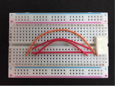
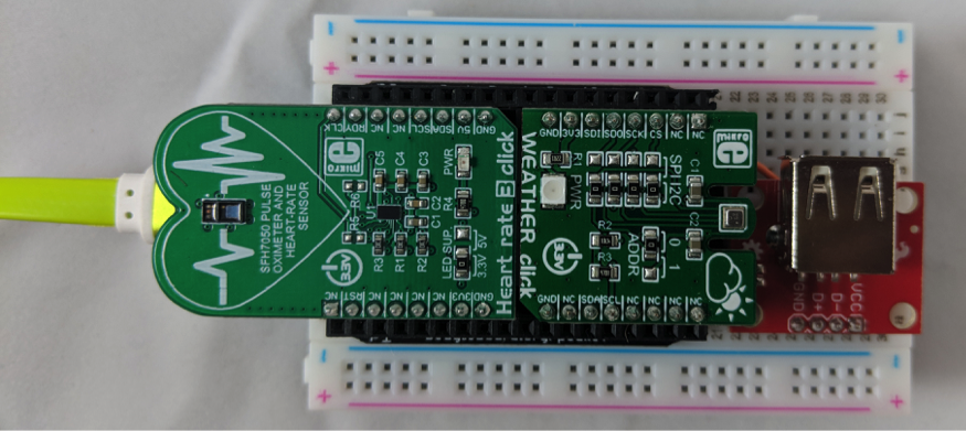
The wiring setup as shown requires the header pin 1 of PocketBeagle® to be inserted in Row 2 and the USB breakout board header pin 1 to be inserted in Row 25. Please note that while the power (VBUS) and ground (GND) wires can be different lengths, the D+/D- wires (i.e. the two middle wires) should be the same length. Additionally, a piece of double-sided sticky foam was placed on the breadboard to provide mechanical support to the USB breakout board. Hence, our final hardware setup can be seen in Figure 4.
Software Needed for Health Monitor Prototype
PocketBeagle® and MikroElektronika Click Boards™ make not only prototyping the hardware easy but make developing the software easy as well. PocketBeagle® can run a Debian Linux distribution that includes support for many different programming languages. Additionally, MikroElektronika Click Boards™ have many software libraries developed around their hardware, which makes interfacing and using the features of the board extremely easy. For our health monitor protype, we will use an Open Source software Python library for the BMP280 from Adafruit. Additionally, we can easily create a Python Library for the AFE4404 from the MikroElektronika C library. This will allow us to get the necessary data from the sensors. From there, it is easy to develop a small networking program that can send the data to the IoT gateway for collection and analysis.
The BMP280 and AFE4404 are connected to the OSD335x-SM over I2C channels 1 and 2 respectively. There are three distinct functionalities that the software needs to implement:
- Measure heart rate data from AFE4404 on I2C2
- Measure temperature and humidity data from BMP280 on I2C1
- Send measured data to an IoT gateway over WiFi
To measure the heart rate, the AFE4404 contains the value of LED1 compensated with the ambient feedback measurement, which is used to generate the PPG signal. To setup the sampling phases for each measurement, we must setup the LED settings, amplifier gain settings, and sampling time/averaging measurements. The PPG measurement is made at a 100Hz and is passed to a moving window based heart rate measurement algorithm. The resultant heart rate data is averaged to update the heart rate every 7 seconds. The combination of the heart rate, temperature, and humidity measurement is then sent to the IoT gateway as a character string over WiFi through a network socket. This data can then be stored, analyzed, or displayed at the gateway or sent to the cloud. This data transfer architecture is extensible such that the IoT gateway can receive measurements/information from multiple health monitors.
Source Project and Resources
This project shows how easy it is to prototype IoT measurement systems taking advantage of the availability of low cost and easy to use open hardware and open software resources. Please follow the instructions on our Hackster page for this project to replicate the setup and prototype an OSD335x based health monitor system of your own.
Get updates to the Health Monitor and all of the IoT Gateway projects
"*" indicates required fields
