
Rapidly Prototype with the OSD3358
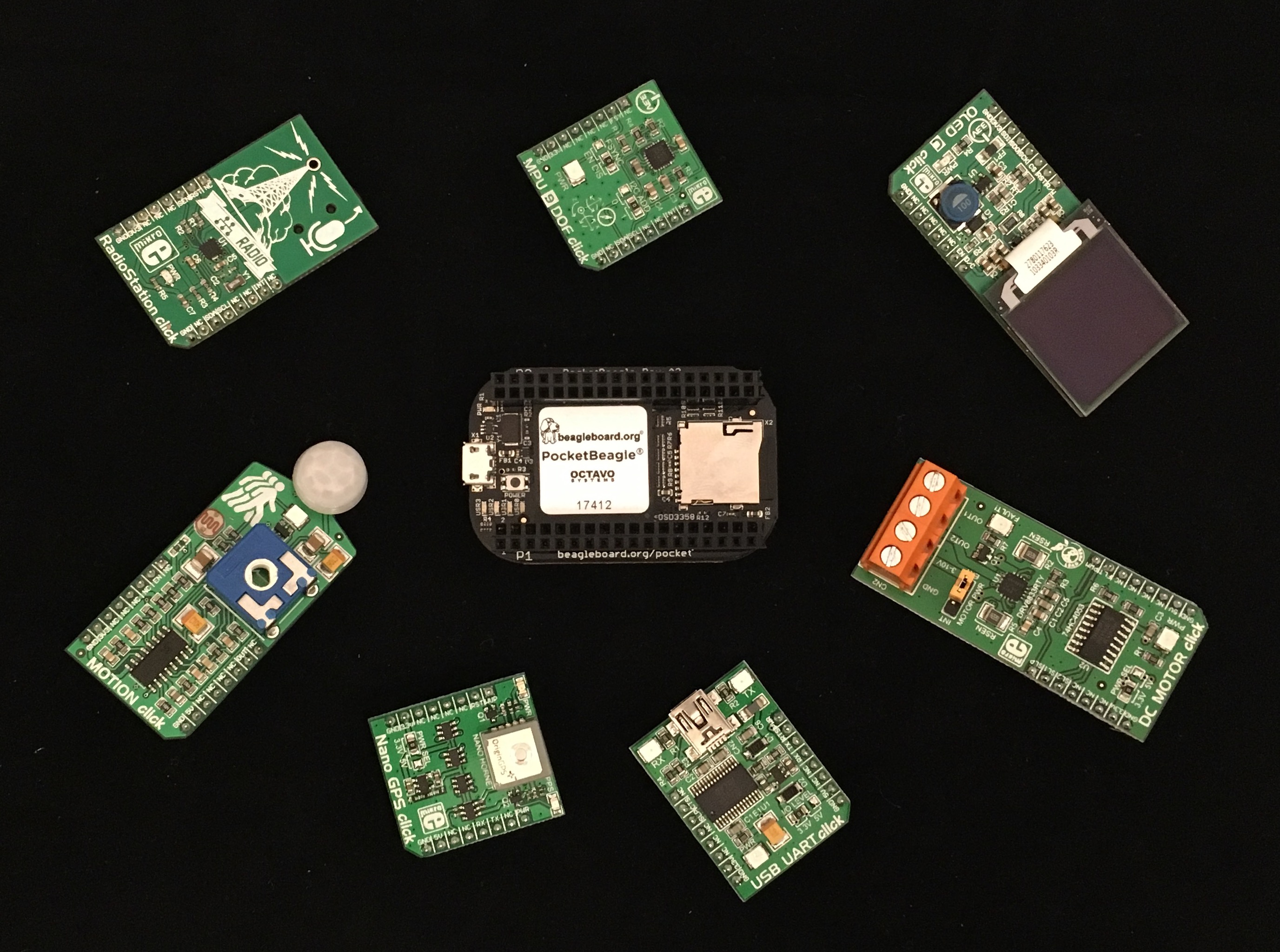
Developers can now rapidly prototype with the OSD3358 System-in-Package (SiP) using BeagleBoard.org® PocketBeagle® and MikroElektronika click boards™. This blog will describe the procedure for interfacing a new click board™ with PocketBeagle® using the OLED-C click board™ as an example. BeagleBoard.org® is a 501c3 Foundation focused on education. PocketBeagle® is a completely open source, highly affordable super tiny single board computer featuring the OSD335x-SM SiP. One of the most exciting things about the BeagleBoard.org® PocketBeagle® is that is conforms to the standard of the MikroElektronika mikroBUS™ click boards™.
There is a Hackster.io project page with the instructions for you to follow along, download the code and build your own project with this great learning platform. We’ve also added a Hackster.io project page with full instructions to build, test and add device tree overlays to BeagleBoard. org® bb.org community repository for click boards™ if you are adding a new one.
Click Boards™
Created by MikroElektronika, mikroBUS™ is an open standard interface for which over 400 compatible add-on boards have been created. These standardized compact boards provide a range of added functionality and features from sensors to connectivity and storage. Click boards™ are MikroElectronika’s brand of mikroBUS™ add-on boards. Using these boards as a way to prototype your new embedded system provides a fast way to try out new features. The software needed to interface the add-on boards to PocketBeagle®, relies on the open source community. Custom device tree overlays and support for a growing number of the click boards™ are available at: https://github.com/beagleboard/pocketbeagle/wiki/Click-boards%E2%84%A2.
Interfacing to BeagleBoard.org® PocketBeagle®
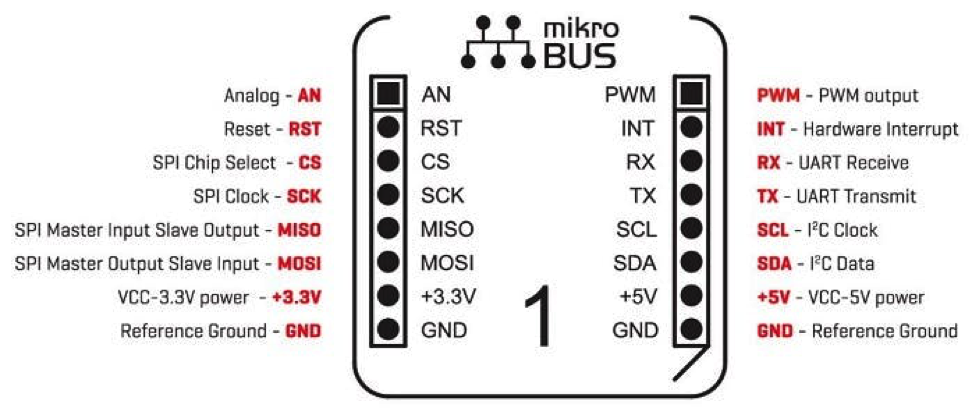
The standard mikroBUS™ interface that is used by click boards™ is shown below. The standard has a UART interface, a I2C interface, a SPI interface, power and ground, an analog input, pwm output as well as some GPIOs for interrupts and reset. These connections are used to interface with the hardware present on the “clicks”. PocketBeagle® headers are designed to allow two clicks to be used simultaneously.
To use a click board™ the following software components needed:
- A Linux driver for the hardware on the click board™
- A device tree overlay
- Application level software to interact with the hardware in the click board™
Linux Driver
Most integrated circuit (IC) manufacturers provide Linux drivers for their devices. For example, the OLED-C click has a SSD1351 driver IC to control the screen. You can find the Linux driver available for this device in the mainline Linux repository at: https://github.com/torvalds/linux/blob/master/drivers/staging/fbtft/fb_ssd1351.c. However, other devices may not have drivers already in the mainline Linux repository. This might require compilation and installation drivers on the board. Unfortunately, not all devices come with Linux drivers. In this case, you will either need to create your own custom drivers or select another, better supported device. Good resources and training is available from the Embedded Apprentice Linux Engineer program to understand, build and debug kernel drivers/modules. See e-ale.org for more information.
Device Tree Overlay
A device tree is a tree data structure that describes the hardware configuration of the system to the Linux operating system. During boot, the Linux kernel will use the information in the device tree to recognize, load appropriate drivers and manage the hardware devices in the system. A good tutorial for understanding, compiling and building new device trees is available in the OSD335x Design Tutorial Series: https://octavosystems.com/app_notes/osd335x-design-tutorial/osd335x-lesson-2-minimal-linux-boot/linux-device-tree/.
A major limitation facing a device tree is that it is static. That is, you cannot change the device tree structure without changing files and rebooting the device. The solution to this limitation comes in the form of Device Tree Overlays. These allow device trees to be dynamically updated to reflect the updated hardware configuration of the system. A great resource for understanding and building device tree overlays can be found in the OSD335x Design Tutorial Series: https://octavosystems.com/app_notes/osd335x-design-tutorial/osd335x-lesson-2-minimal-linux-boot/linux-device-tree-overlay/
Following the methodology for building device tree overlays described in the tutorial series, you can to build a device tree overlay file using the device tree bindings. The SSD1351 device has an SPI interface and the SPI1 interface is exposed on header P2 of PocketBeagle®. So, the device tree fragment for the driver IC would look like the following:
1 2 3 4 5 6 7 8 9 10 11 12 13 14 15 16 17 18 19 20 21 22 23 24 25 26 27 28 29 30 31 32 33 34 35 36 37 38 39 | fragment@1 { target = <&spi1>; __overlay__ { #address-cells = <1>; #size-cells = <0>; status = "okay"; channel@0 { status = "disabled"; }; channel@1 { status = "disabled"; }; mikroe_oledc: mikroe_oledc@0{ compatible = "solomon,ssd1351"; pinctrl-names = "default"; pinctrl-0 = < &P2_31_spi_cs_pin &P2_29_spi_sclk_pin &P2_27_spi_pin &P2_25_spi_pin &P1_36_gpio_pin &P2_33_gpio_pin >; spi-max-frequency = <6000000>; width = <128>; height = <128>; fps = <20>; reg = <0>; regwidth = <0x8>; grb; buswidth = <8>; backlight = <2>; debug = <3>; reset-gpios = <&gpio1 13 0>; dc-gpios = <&gpio3 14 0>; }; }; |
Note that there are several node properties that serve as inputs to the driver through the device tree overlay. Here we are setting the width and height of the display along with the communication speed and additional pins required for the driver to work.
In addition to this fragment, the click board™ has an enable pin that controls the OLED screen. This pin is connected to PIN P1_34 (GPIO 26) of PocketBeagle®. This is declared in another fragment as a GPIO and will be used to turn the screen on and off when desired by the application. The device tree overlay fragment is shown below:
1 2 3 4 5 6 7 8 9 10 11 12 13 14 15 16 17 18 | fragment@2 { target = <&ocp>; __overlay__ { cape-universal@1 { compatible = "gpio-of-helper"; status = "okay"; pinctrl-names = "default"; pinctrl-0 = <>; P1_34 { gpio-name = "P1_34"; gpio = <&gpio0 26 0>; output; dir-changeable; }; }; }; }; |
Compiling and Setting the Device Tree Overlay
A device tree overlay compiling tool that can be used to create, compile and install custom device tree overlays on PocketBeagle® is available from the Beagleboard.org® community. Here is the procedure to use the tool:
1 | $ git clone https://github.com/beagleboard/bb.org-overlays |
- Clone bb.org-overlays to PocketBeagle®.
- Copy the device tree overlay file into src/arm directory of the cloned repository
1 2 3 | $ cp decive-tree-overlay.dts ./bb.org-overlays/src/arm $ cd bb.org-overlays $ sudo make |
- make (This will compile all the device tree overlays in the src/arm directory)
- Correct any compilation errors and make install
1 | $ sudo make install |
The last step will copy the compiled overlays into /lib/firmware directory.
- Finally, a variable uboot_overlay_add(x) needs to be specified in /boot/uEnv.txt to be the filename of the compiled overlay file.
1 2 3 4 5 6 7 8 9 10 11 12 13 14 | ###Master Enable enable_uboot_overlays=1 ### ###Overide capes with eeprom #uboot_overlay_addr0=/lib/firmware/<file0>.dtbo #uboot_overlay_addr1=/lib/firmware/<file1>.dtbo #uboot_overlay_addr2=/lib/firmware/<file2>.dtbo #uboot_overlay_addr3=/lib/firmware/<file3>.dtbo ### ###Additional custom capes uboot_overlay_addr4=/lib/firmware/PB_SPI1_OLEDC_click.dtbo #uboot_overlay_addr5=/lib/firmware/<file5>.dtbo #uboot_overlay_addr6=/lib/firmware/<file6>.dtbo #uboot_overlay_addr7=/lib/firmware/<file7>.dtbo |
- Reboot the board after saving the uEnv.txt file
1 | $ sudo reboot |
Application Software
The application software consists of all the code that interacts with the driver and provides an interface to the hardware on the click board™.
For the OLED-C board we first need to enable the screen to use it to display something. The device tree overlay fragment exposes gpio26 to sysfs interface in /sys/class/gpio folder. The gpio can be turned on and off by manipulating the value file in the sysfs entry of gpio26. Once the value ‘1’ is written into this file, the LED screen will turn on.
1 | $ echo 1 > /sys/class/gpio/gpio26/value |
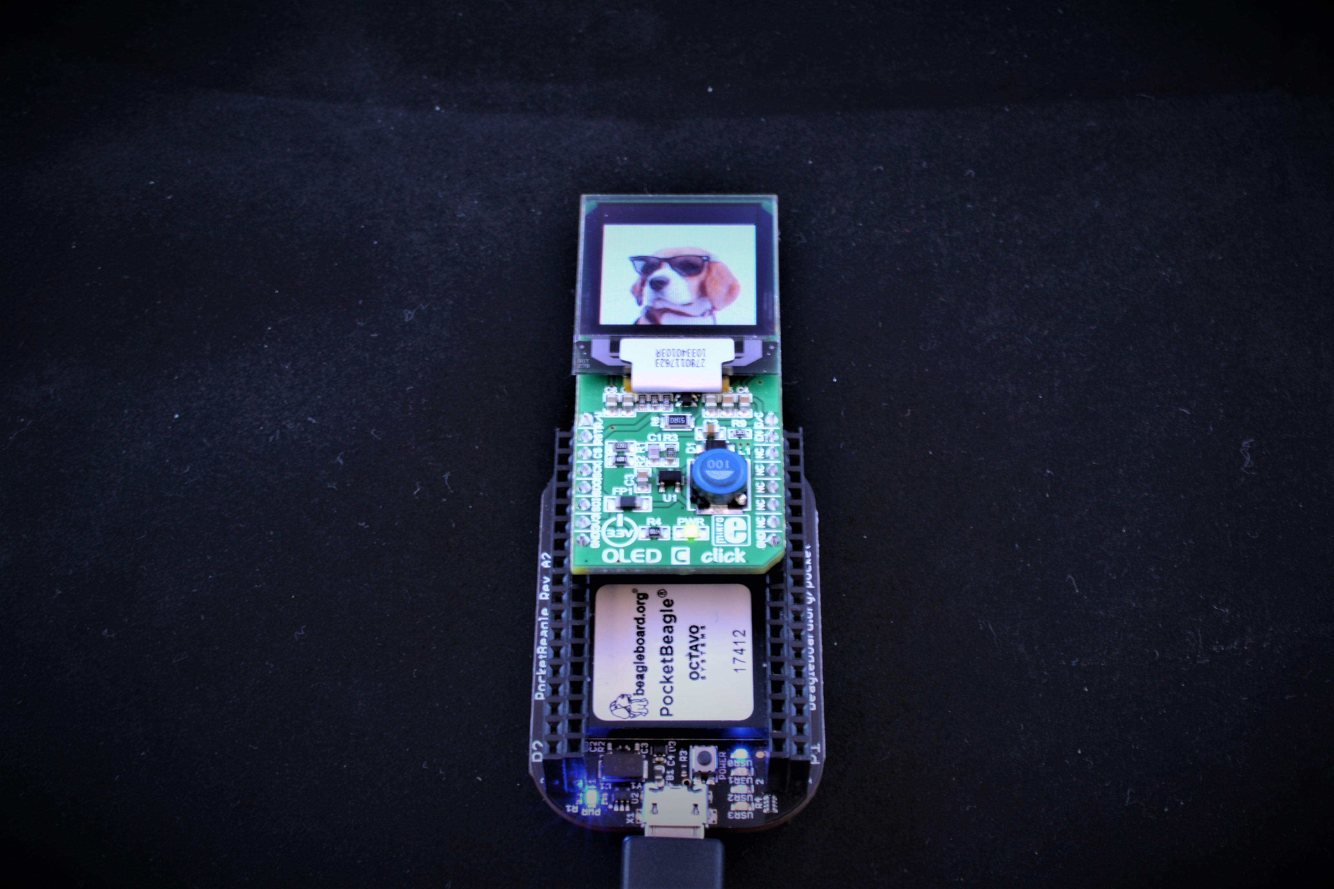
One example application software for the OLED-C click board is FBI (Frame Buffer Image viewer). It is a command line tool used to display images on screens. FBI takes an image file name as the input and displays the image on the OLED-C board. The fbi command can be used to display an image as shown below:
1 | $ sudo fbi -T 1 -a beagleblue.png |
Conclusion
The ease of interfacing of click boards™ to PocketBeagle® from BeagleBoard.org® adds tremendous value to the already popular open source hardware system. Using device tree overlays and open source drivers available for the hardware makes it easy to develop new applications. This style of rapid prototyping takes much less effort than the software and hardware development used by traditional microcontroller-based systems by leveraging the power of Linux.
We encourage you to visit the Hackster.io project page with the instructions for you to follow along, download the code and build your own project with this great learning platform.
We would love to get your feedback on more click board examples you’d like to see.

One thought on “Rapidly Prototype with the OSD3358”
Comments are closed.