HVAC Controller Design Using AM335x Based System in Package
Published On: June, 25, 2019 By: Calvin Slater | Updated: September 1, 2019 by Cathleen Wicks
Part 4: Designing for System Deployment
This is the final part of the HVAC Controller Design Using AM335x Based System in Package. In this part of the series, we will cover designing for mass installation and power-loss contingencies by including device configuration encoders and real-time clock systems. We will also walk through the final design steps and considerations for board layout. We will conclude with a final system block diagram and cover designing for modularity to expand this reference design beyond HVAC to other building automation system controller applications.
For reference, in Part 1 of the series we discussed the System in Package device, the OSD335x family of System-in-Package products featuring the AM335x, as an excellent foundation for the design of an Open-Hardware HVAC Controller. The reference design write up covered the evaluation of the controller board processor system and design specifications. In Part 2 of the series, we investigated the Communications and I/O of the system including RS-485 and CAN Bus. We also discussed the need for a system to be both responsive and flexible due to ever changing standards and increasing capabilities of communication protocols. In Part 3 of the series, we identified vital power considerations for an HVAC controller such as designing the power supply and implementing protection .
For more introductory background, please see the blog article Open-Hardware Building Automation System Controller Reference Design Using AM335x Based System in Package.
Table of Contents
1.Introduction
2.Designing for Installation and Power-Loss
2.1 Rotary Decimal Encoders and Dip Switches
2.1.1 Planning for Initial Configuration, Installation and Maintenance
2.1.2 Using a Serial Shift Register to Manage GPIO
2.2 Real Time Clock System
2.2.1 The Need for a Real Time Clock (RTC) System
2.2.2 Choosing RTC Specifications
3. Finalizing the Design
3.1 Pre-plan Layout Using Ball Maps
3.2 Designing for Modularity
3.3 Expanding Modules for New Applications
4. Concluding Remarks
4.1 Introducing the OSD335x C-SiP
5. About our Guest Author
6. Revision History of this Document
![]()
![]() A PDF version of this App Note can be found here.
A PDF version of this App Note can be found here.

2 Designing HVAC Controllers for Installation and Power-Loss
Only two board peripherals remain before we arrive at a complete design: configuration switches and a real-time clock system. These are small but important components of the board. Basic configuration switches, which facilitate device integration into a network, allow for efficient system scaling by simplifying the installation process. Real-time clock systems guarantee the device will properly resume operation after a loss of power, without the presence of a functioning network or operator intervention. Combined, these two peripherals reduce installation costs for large networks and reduce down-time by automatically restarting after a power outage.
2.1 Rotary Decimal Encoders and Dip Switches
2.1.1 Planning for Initial Configuration, Installation and Maintenance
The most important consideration before deploying large numbers of these type of IoT devices is installation workflow. When commissioning one or two devices it is easy enough for the operator to manually enter the initial settings such as a static IP address and other equipment identifiers. When this same task must be done for hundreds of devices at once, the chore of initial configuration becomes a lot more cumbersome and time consuming. At startup, each HVAC controller will be in a default low-security initial un-configured state. Each device needs some type of unique identifier so that it can be found on the network automatically and then receive the configuration data that was meant for it. An important concept to keep in mind regarding the deployment of these devices is that the person who ends up programming and configuring the device is usually not the same person who physically installs it. In addition, these two activities are usually performed at distinctly separate times. Manual configuration under these conditions becomes even more difficult and error prone.
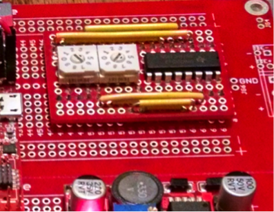
Rotary decimal-based encoder switches (See Figure 1) are a convenient method to assign a unique identification number to a device during installation. This device ID then enables easy identification of any specific HVAC controller and piece of equipment during startup and commissioning of a HVAC controller network segment. The addition of two rotary encoders can be used to address and identify up to 100 devices per HVAC controller. This should be an adequate number for any particular network segment of a building. Rotary switches are also preferable to dip switches, the more commonly used device which uses binary place positions. While dip switches are cheaper than rotary encoders, they are a lot less convenient to use and error prone. Most people do not count in binary, making it prohibitively difficult to glance at a set of dip switches and quickly determine if a particular HVAC controller has the correct unique address. Dip switches are best used for other kinds of initial configuration settings.
2.1.2 Using a Serial Shift Register to Manage GPIO
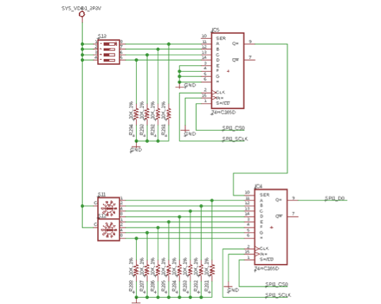
Encoders and switches would consume far too many GPIO pins if one was assigned for every bit. Each rotary encoder would require 4 pins to represent 4 bits. This would be a terrible waste of GPIO especially considering these configuration settings would be read infrequently, possibly at device startup only. A good way to preserve GPIO pins is to use serial shift registers. Shift registers convert data between serial and parallel formats. The HC165 shift register can be used to shift data into the OSD and the HC595 can be used to shift data out. Each shift register can convert 8-bits of data from parallel into serial form or vice versa. The input of a shift register can be attached to the output of another so that all bits can be shifted into or out of one I/O port. Of course, this serial data will have to be decoded in program code using bitwise operations. More information on this topic can be found in chapter 9 of Exploring BeagleBone: Tools and Techniques for Building with Embedded Linux by Derek Molloy .
For this design we will use two decimal rotary encoders and one four-position dip switch. See Figure 2. This will require 12 bits so we will need two HC165 shift registers connected in series to shift all of the bits in at once. Doing so will only consume three pins on the OSD; one for the data, one to strobe the data in and a final pin to control the load/shift mode. On any bus (SPI, manual strobing, etc.), each connected IC must be in a known active or inactive state. Since there are no other peripherals connected to this interface, we will set both shift registers as always enabled.
2.2 Real Time Clock System for HVAC Controllers
2.2.1 The Need for a Real Time Clock (RTC) System
The real time clock peripheral is a critical component that many building automation devices lack. Many current production offerings rely on time-sync services from another gateway or server device. For example, an Air Conditioner unit might have several months of scheduled run times loaded into its non-volatile storage. After an outage, as the power comes back online, the HVAC controller will need to read from its schedules and continue to run. This is not possible if the device does not know the time and date. The HVAC controller must have the flexibility to operate in standalone mode if required. If there is an outage, the device needs to be able to resume its assigned task(s) without waiting for a network time update from a server which may not always be available. A real-time clock systems allows the device to independently know the date and time and resume its task immediately.
2.2.2 Choosing RTC Specifications
Real Time clock systems are rated in units of Parts Per Million (ppm). If a device is accurate to ±1ppm then it will be accurate to within one system tick for every one million ticks, which would give a range between 999,999 to 1,000,001. A better way to think of this is in terms of seconds. There are about 2.6 million seconds in a month. A ±1ppm device can potentially be off by 2.6 seconds every month. This potential error would be more than acceptable for something like an Air Conditioner unit schedule. The threshold where reasonably good accuracy begins is generally considered to be ±20ppm. Such a system would only deviate by about 1 minute if left offline for a month with no network updates. Of course if the device is to operate stand-alone, a clock system with much better accuracy would be required.
For this design we will be using an external real-time clock module. The AM3358 processor has its own internal real-time clock module which can be used when the SiP is powered up, however the TPS65217C does not support RTC only mode for when the SiP is powered down. An additional external real-time clock will be needed for this purpose. When the device is not powered, the external clock will be kept running by a 3.3V CR2032 battery. This will allow the device to instantly know the correct time when back online, even after extended outages. We will be using the Maxim DS3231M which is the same RTC used on the Sparkfun Cryptocape. This is a very nice device that maintains accuracy to ±3ppm in extended temperature conditions. It maintains accuracy using internal temperature compensation circuity making additional temperature sensors and compensating code unnecessary. It does not require an external 32kHz oscillator crystal. Not only that, the internal oscillator can be used as a reference for other devices. We will connect the output of this RTC to the single ended input of the OSD. This will allow for the elimination of the second external crystal for the OSD’s real time clock on the RED board.
3. Finalizing the Design
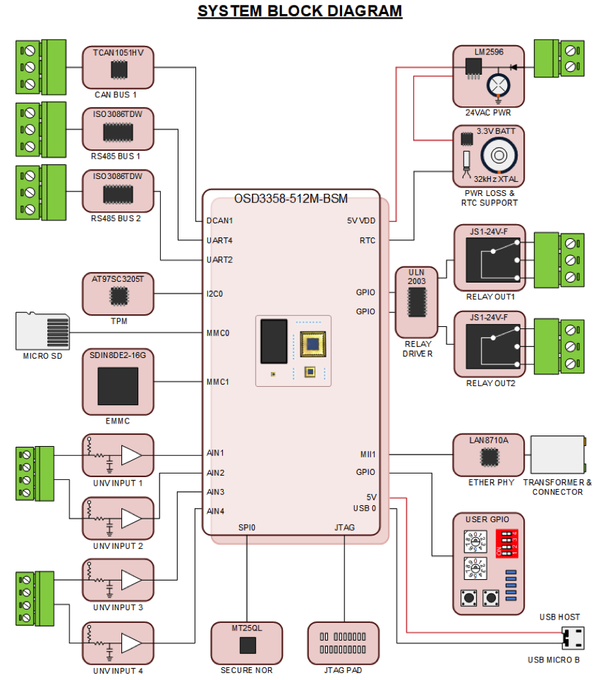
The addition of the encoders and RTC brings us to the end of our system design, resulting in the system block diagram shown below in Figure 3. This meets the specifications laid out in part 1 and incorporates all design considerations addressed up until now. Now, we will implement this in a board schematic and layout suitable for the building automation application.
3.1 Pre-Plan Layout Using Ball Maps
Now that all of the different subsystems have been introduced we will discuss how these elements should be integrated into a single design. A good starting point when planning a layout with any OSD SiP is to take a look at the color-coded ball maps provided by Octavo Systems:

These maps, like the one shown in Figure 1 from section 3.2 of the OSD335x C-SiP Layout Guide, are very good to help pre-plan your layout. Observe the locations of the dedicated peripheral pins and then decide the best orientation and position of the SiP on your board.
3.2 Designing for Modularity
One of the original objectives of this project was for the board to have a modular design. Various subsystems should be able to be added or deleted without greatly affecting the layout of remaining components. It should also be possible easily add or remove multiple instances of the same type of peripheral. For example we can have one or two RS-485 ports. The best way to accomplish this goal is to try to keep all related components for a particular subsystem grouped closely together on the board layout where possible.
Modules that contain noise sensitive analog circuitry will be at the bottom of the board in a section that has its own analog ground plane (AGND). Isolation of the analog front end is important to avoid the acquisition of noise due to the activity of other circuits. In general we want to avoid a layout where other signals transverse the region containing analog modules. A great discussion of how to layout analog circuits and grounding can be found in this third party blog..
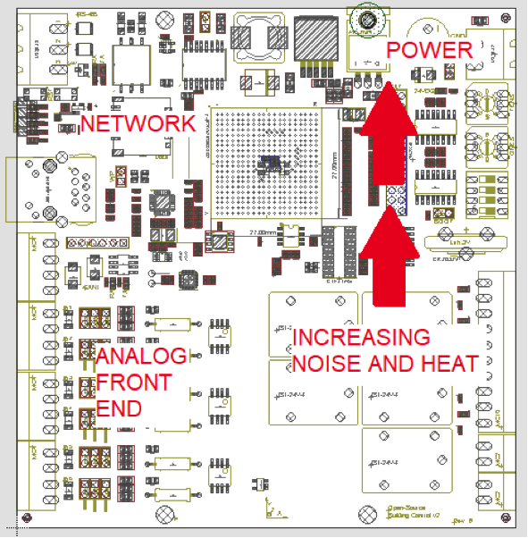
Noise sensitive circuits should be kept as far away from noise producing devices where possible. In this case the potential sources of noise will be from the power management circuits, transformers, inductors, and networking interfaces. All of these devices will be located far away from the analog interfaces at the top of the board. Also located at the top of the board will be the heat generating devices, mainly the voltage regulators VREG1-3. In general it is a best practice to locate the components on the board in the direction of an increasing thermal gradient upward. This will encourage good convective cooling with our heat sensitive analog circuitry receiving the coolest possible air. See Figure 5.
3.3 Expanding Modules for New Applications
The big-picture plan is for this board to be the first in a series of several building automation related devices. There will be other future versions that have application specific peripherals built on to the board. For example one future board will have an integrated airflow sensors for volumetric air control. Another will feature current and voltage sensing apparatus for electric metering. For the purpose of creating a family of such devices, we should separate the peripherals common to all devices from the application specific ones.
The peripherals common to all devices will be:
- Network Ports; Ethernet, RS-485, CAN, UART, USB.
- Non-Volatile Storage; EMMC, SD Card.
- Real time clock, TPM, Secure NOR.
- System Status Lights and Configuration Switches.
- 24VAC power with possible PoE variants.
Application specific device peripherals will include:
- Universal Inputs
- Relay Outputs
- Analog Outputs (Future)
- Electric Metering Front End (Future)
- Damper and Valve Actuators (Future)
- Integrated Airflow Sensing (Future)
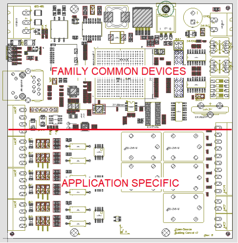
We will separate the application specific peripherals from the family-common ones by locating the SiP and all common devices together on the top of the board. The application specific devices will be on the bottom half. See Figure 5. As application specific peripherals are added or removed, the board can grow in size downward while maintaining a consistent board width across the family of devices. Where the application specific input and output connectors are concerned, we will keep the process inputs located on the left side, and process outputs on the right.
4. Concluding Remarks
While we presented this reference design in a rather lengthy four-part application note to cover all system details, designing with the OSD335x, AM335x Based System in Package itself is relatively easy. In fact most of the series was not spent talking about the processor at all, that’s because it just works. We were able to simply drop the basic processing system SiP, with all its SOC integration (memory, power, discretes, etc.), into the design and spend time focused on the board’s actual application and function. The Octavo Systems OSD335x System in Package, tested and guaranteed, provides a known good starting point, leaving only the application-specific work to be done and eliminating much of the uncertainty with fabricating a first prototype.
4.1 Introducing the OSD335x C-SiP
The OSD335x C-SiP consolidates the basic processing system even further then the OSD335x-SM used in this application. This new member of the OSD335x Family of System in Package devices eliminates the need to source and integrate external EMMC as well as the main oscillator circuitry. It is preferable to move these critical components into the SiP enclosure, especially for industrial applications where the introduction of contaminants onto the board is likely. Even though the package of the C-SiP is a bit wider than the OSD335x-SM, the overall effect of moving the EMMC and oscillator inside the package actually preserves board space.
At the time of posting for this application note, the first prototype board is in fabrication. There are two sets of design files for this project. They both can be found in my Github repository for this project. The first design uses the OSD3358-512M-BSM. The second design which features a much improved board layout uses the OSD3358-512M-ICB, which is the industrial temperature rated version of the C-SiP. Due to the advantages of the new C-SiP along with the improved layout, the C-SiP version is being fabricated first. Please stay tuned to this post in the forums. Once the first prototype arrives from fabrication, I will post the results and show board bring-up there.
5 About our Guest Author
This article was guest written by Calvin Slater who is a senior controls engineer that has spent eight years in the Building Automation System Control Industry and is highly interested in embedded hardware as well as open-source building automation frameworks. He is also a contributing editor for AutomatedBuildings.com where he has authored a series of articles on the system edge controller.
6. Revision History
| Revision Number | Revision Date | Changes | Author |
|---|---|---|---|
| 1 | 6/24/2019 | Initial Release | Calvin Slater |
| Return to “Part 3 : Power and Protection Considerations” | Return to “Part 1 : Design Requirements and Baseboard Overview” >> |
