Building Automation System Controller Reference Design
Forums › Reference, Evaluation, and Development Boards › Building Automation System Controller Reference Design
- AuthorPosts
- July 10, 2019 at 10:21 am #8620

 Calvin SlaterParticipant
Just got this prototype board back from the fab.
I chose to mount most of the PTH components myself to save some money, and because soldering is fun!
This board will look a lot different when all the connectors and relays are on.
Attachments:
- July 16, 2019 at 1:51 pm #8653Calvin SlaterParticipant
I made this board as close to the Beaglebone Black™ as possible with regard to the same peripheral devices and pin compatibility.
This board should run BB Debian Images directly with no modifications.
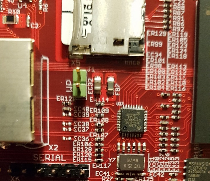
If you are planning to do the same with your project, make sure your PCB design gives you access to the I2C bus EEPROM that is on the OSD SiP. Most importantly make sure you give yourself access to the EEPROM Write Protect (EEPROM_WP) pin. You will need to ground this pin to program your EEPROM with the correct data.
A great discussion of this subject can be found here:
Attachments:
- July 22, 2019 at 11:14 pm #8726Calvin SlaterParticipant
This building controller has the EEPROM programmed to think it’s a BBB right now.
Currently running a BBB Debian IoT image from the SD card. Its amazing how everything just works right out of the box!
Attachments:
- August 6, 2019 at 2:02 pm #8829Calvin SlaterParticipant
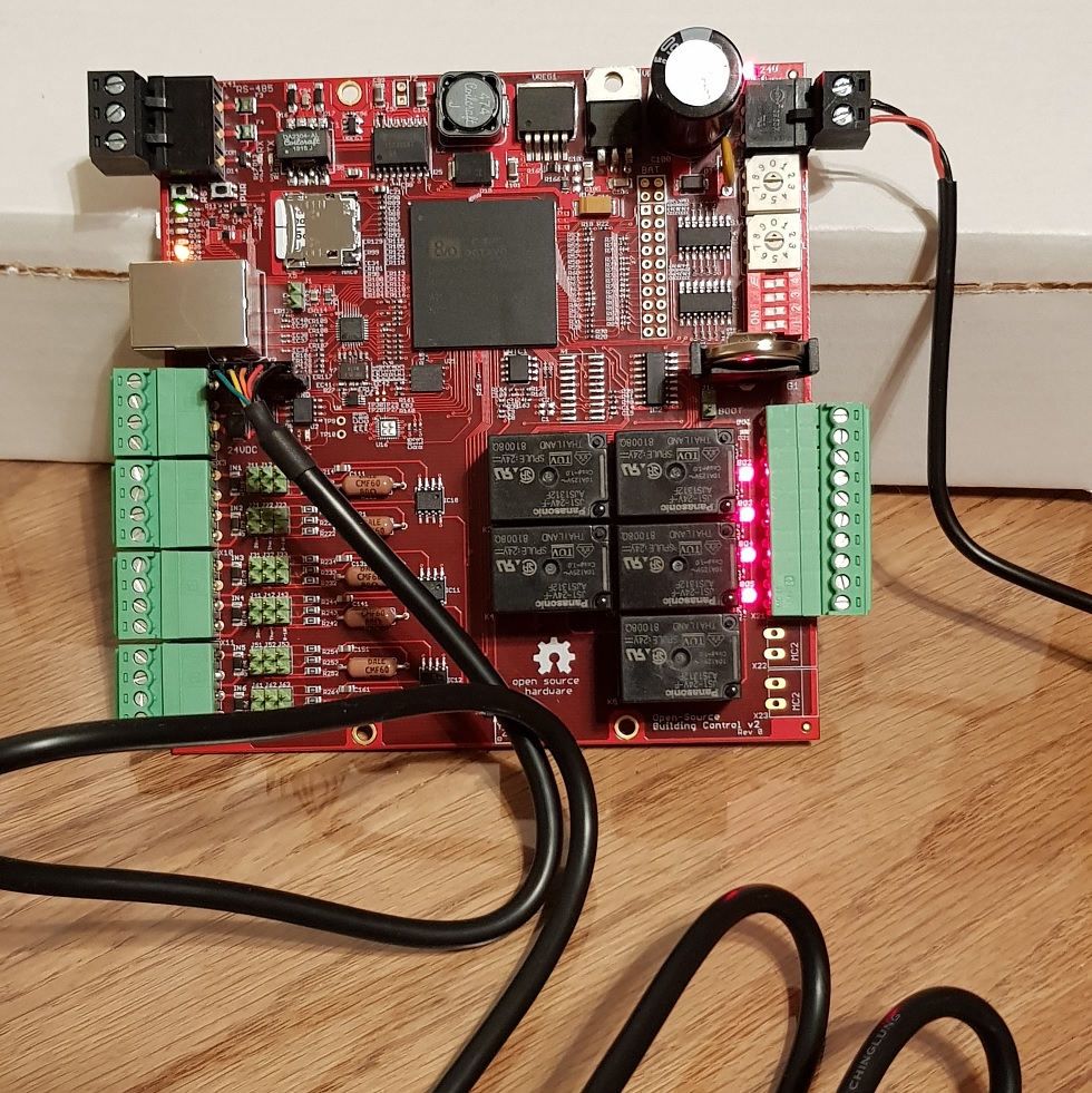
Relay Outputs seem to be working well.
Thinking about moving BO1 to a different GPIO (GPIO1_17) in the next revision so that there would not have to be any changes to the default device tree from BBB.
A good tip I got from Octavo:
When selecting GPIO pins for any particular task, pay attentions to the pin’s ball reset state on the AM3358 datasheet.
http://www.ti.com/lit/ds/symlink/am3352.pdf
For example, I would not want relay outputs to reset high for this board, therefore all of the pins selected on this board for relays reset low.
Attachments:
- September 22, 2019 at 10:21 pm #9113Calvin SlaterParticipant
The serial-loaded user configuration switches using SPI1 to shift data in seem to work well.
The data of interest is the first two characters (or octets) only. with the first octet being the decimal rotary switch positions followed by the positions of the four dip switches. When shifting in data this way, the information contained will be parsed using bitwise operations in code.
A couple of notes:
When shifting in data using an HC165 registers remember to set CS0 to HIGH to transition from parallel-load to shift mode.
On some of the tests using spidev_test.c, the remaining characters contained gibberish values. This is probably because I left SER IN on IC5 floating. This pin will be grounded in the next revision.
Attachments:
- December 29, 2019 at 1:40 am #9605Calvin SlaterParticipant
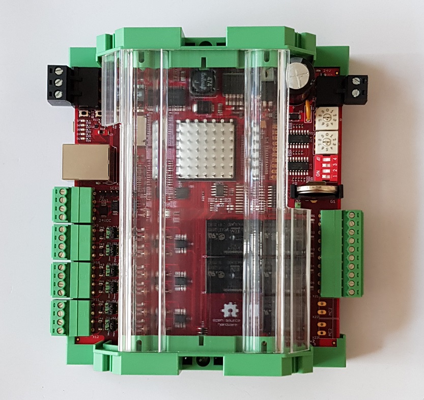
Choice of enclosure for this board is up to the user.
I put this one together using 122mm wide DIN rail mounts with a clear plastic cover.
The green and red go good together I think.
Attachments:
- December 30, 2019 at 10:17 pm #9610
 Neeraj DantuModerator
Looks great! Thanks for all the updates!!
Neeraj
- January 7, 2020 at 1:28 pm #9621Calvin SlaterParticipant
Thank you Neeraj for making great chips!
New Revision 2.1 board back from the fab.
Time to do some more soldering!
Attachments:
- AuthorPosts


- You must be logged in to reply to this topic.
