HVAC Controller Design Using AM335x Based System in Package
Published On: March, 29, 2019 By: Calvin Slater | Updated: July 17, 2019 by Greg Sheridan
Part 2: Communications and I/O
In Part 1 of the HVAC Controller Design Using AM335x Based System in Package we discussed the System in Package device, the OSD335x family of System-in-Package products featuring the AM335x, as an excellent foundation for the design of an Open-Hardware HVAC Controller. The reference design write up covered the evaluation of the HVAC controller board processor system and design specifications.
In part two of this four part series, communications and Input and Output (I/O) will be our focus. Understanding how the HVAC controller communicates with all the other components is a key portion of building automation designs. Ever changing standards and increasing capabilities of communication protocols require hardware and software that is both responsive and flexible. This article will focus on two main communication protocols; RS-485 and CAN bus, and discuss their importance in building automation design. Additionally, to gather sensor data or control aspects of the building require input to or output from the HVAC controller. This article will focus on Analog Universal Input Modules and Form A Binary Output Relays to accomplish this task and discuss the processor requirements to support these methods.
For more introductory background, please see the blog article Open-Hardware Building Automation System Controller Reference Design Using AM335x Based System in Package
Table of Contents
1.Introduction
2.Communication Protocols
2.1Isolated RS-485 Port
2.1.1Background on Using RS-485
2.1.2Implementing RS-485
2.2CAN Bus Port
2.2.1 Background on Using CAN Bus
2.2.2 CAN Bus Implementation
3.Input and Output (I/O)
3.1Analog Universal Input Modules
3.1.1Typical Sensors in the System
3.1.2Implementation of the Analog Universal Input Modules
3.2Form A Output Relays
3.2.1Importance of Relays in the Design
3.2.2Implementation of the Relays
4.Concluding Remarks
5.About our Guest Author
6.Revision History
![]()
![]() A PDF version of this App Note can be found here. (update)
A PDF version of this App Note can be found here. (update)

2 Communication Protocols needed for HVAC Controller Systems
Communication is an important aspect of life and this is especially true for building automation systems. In order to work in harmony to achieve objectives, like controlling the environment or saving energy, each component in a building automation system must be able to effectively and reliably communicate the necessary information. Today, two main communication protocols are used to do this: RS-485 and CAN (Controller Area Network) bus. This section will provide some background on each protocol as well as discuss implementation details around each protocol that are important to understand when designing a building automation system with AM335x system in package.
2.1 Isolated RS-485 Port
One communication protocol that is commonly used in building automation designs is RS-485. In this section, we will explore some features of RS-485 as well as look at an example implementation that is part of the building automation reference design
2.1.1 Background on Using RS-485
The EIA-485/RS-485 standard forms the Physical Layer for many building automation communication protocol schemes. The RS-485 standard provides an economical method to bring wired network communication to multiple low-end device nodes that are only equipped with a simple UART peripheral. Using only one twisted pair of wires for differential signaling, a peer-to-peer network can be created with multiple nodes (drop) in a linear bus topology.
RS-485 provides robust data communications even in noisy environments. First, RS-485 uses differential signaling and twisted-pair cabling which provide common mode noise rejection. Additionally, the cable contains an isolated reference ground signal, which helps eliminate transmission line ringing due to resonant frequencies formed by ground loops between network nodes. There is also a trade-off between cable length and data rate in that RS-485 can over 1,200m at lower data rates.
RS-485 communication is half-duplex, meaning that both the transmitters and receivers are connected to the same wire. Therefore, only one network node can transmit at a given time. Hence, a Data Link Layer level bus arbitration scheme must be used. Many building automation systems use Token based communication schemes, thus eliminating the need to manage data communication collisions.
2.1.2 Implementing RS-485
Any device that has a UART (Universal Asynchronous Receive/Transmit, a.k.a. serial port) peripheral, can easily implement RS-485. All that is needed is the addition of an appropriate transceiver and supporting circuitry to create a transmission line. The Texas Instruments Sitara™ ARM® Cortex®-A8 AM335x processor within the OSD335x family of System-in-Package products supports up to 6 UART peripherals. For this example design, we will use the UART4 peripheral.
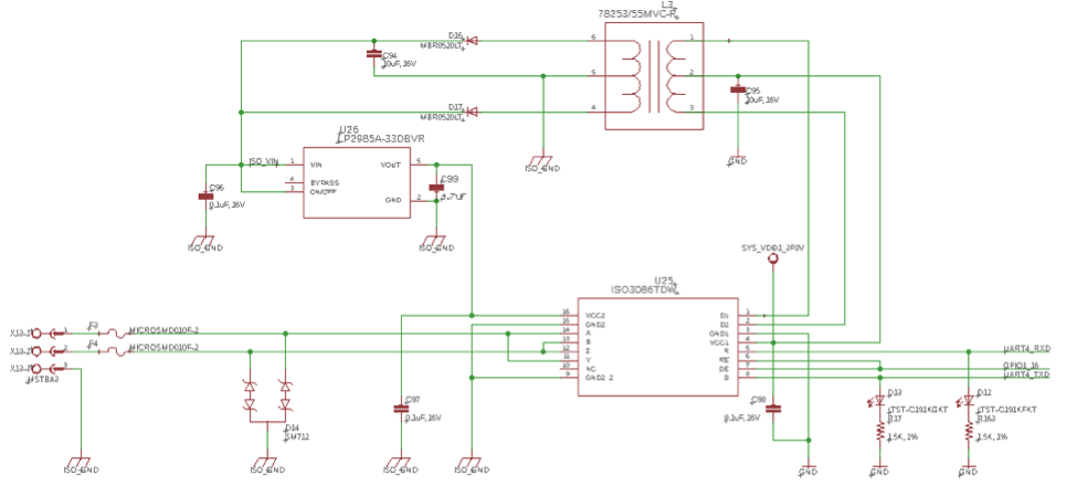
In general, the most robust RS-485 communication circuits are fully isolated. When all devices are connected together, the network forms a long continuous DC circuit which can span several buildings, in some cases. To avoid the effects of mixed electrical domains and help eliminate signal transition ringing, the network lines must be isolated from the device. To accomplish this, our design will use Texas Instruments ISO3086T, Isolated 485 Transceiver with integrated transformer driver. This device provides both full galvanic isolation as well as a primary side oscillator module to drive and power circuitry on the isolated side. Figure 2.1 shows the ISO3086T as well as the additional components (isolation transformer, a low-dropout linear voltage regulator (LDO), and passives) to have a completely isolated RS-485 node. To further increase robustness of the solution, we will add circuit protection devices such as fuses and transient voltage shunt devices. Littlefuse provides an application note (see page 5) for more information. Additionally, a gas discharge tube can be added (not pictured above) to increase robustness in certain environments.
The transmit and receive data lines of the ISO3086T need to be connected to UART peripheral of the OSD335x, in this case UART4. Additionally, a signal to enable/disable the line drivers must also be connected, in this case a general purpose output from the processor, GPIO1_16. Most building automation communication system protocols using RS-485 as the physical layer implement bus arbitration schemes that are non-collision based, such as peer to peer token passing. This means we do not need to detect frame collisions and therefore the Driver Enable (DE) and Receiver Enable Not (~RE) can be controlled using the same signal. Additionally, Transmit (TX) and Receive (RX) LEDs have been added to give a visual indication of port communication.
By implementing this circuit, the HVAC controller now has the ability to robustly communicate over RS-485 as well as provide the operator or technician visual feedback that the system is operation.
2.2 CAN Bus Port
Another communication protocol that is commonly used in building automation designs is the Controller Area Network or CAN bus. In this section, we will explore some features of CAN bus as well as look at an example implementation that is part of the building automation reference design.
2.2.1 Background on Using CAN Bus
CAN Bus was originally developed in the automotive industry to provide robust, easy-to-use communication between various components of a vehicle. Today, it is one of the most commonly used communication protocols in modern vehicles. The CAN bus connects microprocessor-based subsystems throughout a vehicle and is used for remote monitoring and control. The CAN protocol is very robust and features a bus arbitration method that allows for prioritization of data traffic. This makes CAN bus well suited for local real-time control when compared to RS-485 based networks. Therefore, CAN bus has been adopted in many building automation control products.
However, CAN bus cannot support the long transmission distances commonly seen in RS-485 building automation systems. Therefore, a hybrid approach is necessary to take advantage of the strengths of each communication protocol. Typically, building automation systems will use an RS-485 network for long distance inter-controller type communications and then use a CAN Bus network for short distance real-time control communications to components, such as I/O expansion boards, sensors, and actuators.
2.2.2 CAN Bus Implementation
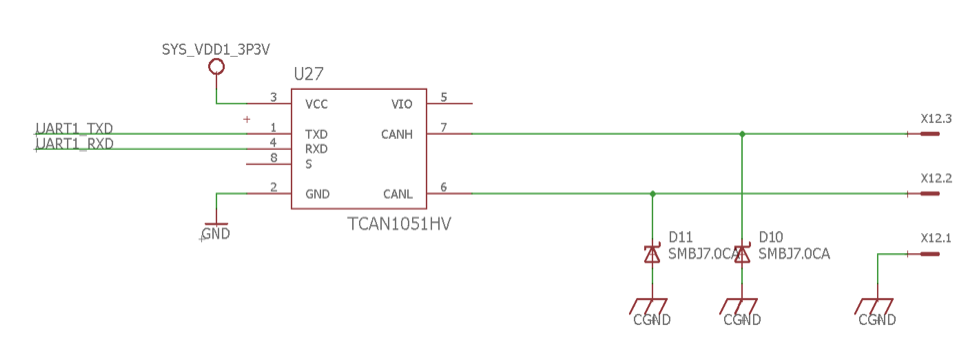
The AM335x processor within the OSD335x System in Package comes equipped with two DCAN (digital CAN) modules that fully support CAN 2.0 A & B protocols. It is extremely easy to implement a CAN Bus network node using the OSD335x SiP as seen in Figure 2.2. All that is needed is the simple addition of a CAN transceiver. For the reference design, we will use the same CAN transceiver that is featured on the BeagleBone Blue, the Texas Instruments TCAN1051H. This transceiver has additional internal protection circuitry to improve the robustness of the CAN communication. In the reference design, we only need to use one of the two DCAN peripherals for our CAN network. Therefore, we chose to use DCAN1 so that we could reuse the device tree information from BeagleBone Blue to enable the DCAN peripheral.
3 Input and Output (I/O)
The most important part of an embedded HVAC controller is the physical inputs and outputs. This allows the controller to gather information about the environment and affect changes to system components. Inputs and Outputs can either be digital (i.e. have a voltage that is interpreted as either a “1” or “0”) or analog (i.e. have a voltage which communicates information based on its value). In this section, we will discuss the use of analog inputs to collect data via Analog Universal Input Modules and the use of digital outputs to control components via Form A Output Relays.
3.1 Analog Universal Input Modules
Unitary controllers of a building automation system that are attached to zone equipment are typically equipped with five or more wired sensor inputs. These sensors typically provide an analog voltage to express the value of the sensor. To interpret these analog voltages, the signal must be run through an Analog to Digital Converter (ADC). In this section, we will look at the typical sensors in a system as well as how to connect these sensors to the OSD335x.
3.1.1 Typical Sensors in the System
In a HVAC controller application, there are a wide variety of sensors used to monitor the environment within the building. Sensors can collect information on conditions such as:
- Space Temperature
- Space CO2 Concentration
- Space Occupancy
- Discharge Air Temperature
- Return Air Temperature
- Fan Status or Fan Current Draw
- Compressor Status or Current Draw
- Damper Feedback
- Dirty Filter Switch or Differential Pressure
Typically, most of these sensors provide analog outputs to communicate the value of the information that is being monitored by the sensor. These analog signals can be affected by noise so it is important that they are properly conditioned and protected so that they can be read by the processor.
3.1.2 Implementation of the Analog Universal Input Modules
Analog sensors can transmit their values using three basic categories of signaling methods:
- Resistance
- Voltage (Typically 0-10V Range)
- Current (Typically 0-20mA)
To receive these signals, simple passive circuitry can be attached with buffers to the ADC input channels of the OSD335x SiP. The maximum voltage of the OSD335x ADC input is 1.8V. Hence, the sensor output will need to be scaled, filtered, and protected. This is shown in Figure 3.1.
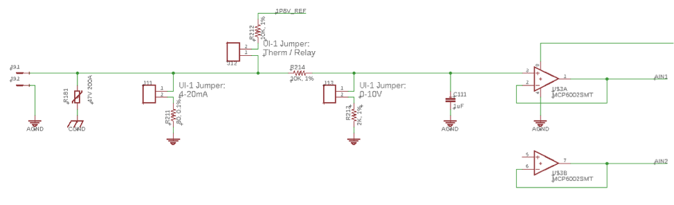
To protect the ADC inputs, a unity gain buffer (U$3A in above picture) will be added to the input of each channel. We used the MCP600x series operational amplifier (op amp) as recommended in the book Exploring BeagleBone. These op amps will be powered by the SYS_ADC_1P8V output rail from the OSD335x, which is connected to the reference voltage, VREFP, of the ADC. SYS_ADC_1P8V is buffered to ensure that the maximum current draw is not exceeded. Using this power rail for the unity gain buffers helps guarantee that the ADC inputs will not be greater than 1.8 volts.
Additionally, there are selectable jumpers (J11, J12, and J13 in above picture) that connect the input to pull-up or pull-down resistors that can scale the voltage or support Resistance/Dry Contact type inputs. For example, a 4mA to 20mA current transmitter signal passing through an 80ohm precision resistor (i.e. jumper J11 is populated; J12 and J13 are not populated) will scale to an input voltage range of 0.32V to 1.60V.
Finally, the 10K ohm resistor (R214) and 1uF capacitor (C111) form a simple low pass filter that will reject any frequency above 16Hz to reduce noise in the input. However, if pulse counting capability is required for signals above 16Hz, the 1uF capacitor (C111) can be replaced with a 0.1uF capacitor. The only caveat with replacing the capacitor is that any 60Hz noise, which can result from the input power supply, will need to be filtered out digitally.
The mapping of data from ADC values to physical values should be a straightforward task in software. If a sensor requires non-linear mapping such as a thermistor, then curve fit calculations or lookup tables can be implemented in software. For more information on the setup of this circuit please refer to Chapter 9 of Exploring BeagleBone. If more than 8 channels of analog are required, then external ADCs can be used and interfaced to the OSD335x over a digital communication bus.
3.2 Form A Output Relays
Relay outputs provide on/off control to remote devices that have currents that are far too great for the general purpose I/O (GPIO) pins of the OSD335x to source or sink. Relays also provide full isolation between the HVAC controller and the device they are controlling. In this section we will look at the importance of relays in building automation systems as well as an implementation of Form A output relays.
3.2.1 Importance of Relays in the Design
Relays are extremely important in building automation systems because they allow a low voltage, low current microprocessor to control devices that require much higher voltages and currents. For example, your home thermostat uses relays to signal your air conditioner’s control board to turn the fan on or off or go into heating or cooling. The air conditioner’s control board requires 24VAC signals in order to change the operating mode. Without relays, the thermostat microprocessor would need to be able to handle 24VAC I/O which would add cost and complexity to the microprocessor. Instead, the thermostat uses a relay contact closure for each signal (a.k.a. dry-contact signaling) to send the 24VAC input voltage supplied by the air conditioner control board back to it. Hence, the microprocessor only has to handle much lower voltages and can be much less expensive.
3.2.2 Implementation of the Relays
This reference design has five relays which is an adequate number of outputs to control most air conditioning equipment as well as other common pieces of equipment used in building automation systems.
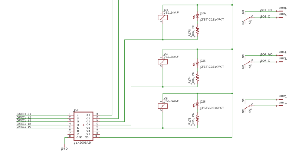
The reference design will be using automotive type 24VDC Relays. These relays can be rated for up to 10A at 120VAC or 5A at 30VDC (Please exercise care and refer to datasheets if using these as power relays to directly control higher voltage equipment). To close the 24VDC relays, 24 volts and 15mA of current is required. Unfortunately, this is more than the GPIO pins of the AM335x processor can source. Therefore, we will have to use transistors (IC2) to supply the current needed to close the relays. Many designs use discrete transistors to drive each relay, but for this design we will consolidate components by using a single transistor array. The ULN2003A is a Darlington transistor array that is commonly used in building automation products to drive relays. There are eight transistor channels on this device which makes it convenient to control more relays if needed. The relay circuit shown in Figure 3.2 may appear confusing at first. However, a good explanation of how this circuit works can be found in this video here. We will use GPIO3_21 as well as GPIO1_12 to GPIO1_15 for our outputs. Additionally, to provide a visual indication if the relay has been activated an orange LED is connected to each output.
4 Concluding Remarks
As we have seen in this article, only a few additional components are required to make the OSD335x System in Package family of devices into a HVAC controller that is able to effectively communicate with and control the other components in a building automation system. In addition to I/O and communications, another important aspect is how these devices receive and condition input power. In the next part of our series will explore the topic of Power management.
5 About our Guest Author
This article was guest written by Calvin Slater who is a senior controls engineer that has spent eight years in the Building Automation System Control Industry and is highly interested in embedded hardware as well as open-source building automation frameworks. He is also a contributing editor for AutomatedBuildings.com where he has authored a series of articles on the system edge controller.
6 Revision History
| Revision Number | Revision Date | Changes | Author |
|---|---|---|---|
| 1 | 3/25/2019 | Initial Release | C. Slater |
| << Return to “Part 1: Design Requirements and Baseboard Overview” | Continue to “Part 3: Power and Protection Considerations” >> |
