HVAC Controller on AM335x System-in-Package
Published On: May, 22, 2019 By: Calvin Slater | Updated: July 17, 2019 by Greg Sheridan
Part 3: Power and Protection Considerations
This is part three of a four part series in which we will discuss HVAC controller power decisions, both in supply of power to the system and protection from unintended electrical disturbances and electrical fields.
In Part 1 of the HVAC Controller Using AM335x Based System in Package series we discussed the System in Package devices, the OSD335x family of System-in-Package products featuring the AM335x, as an excellent foundation for the design of an Open-Hardware HVAC Controller. The reference design write up covered the evaluation of the controller board processor system and design specifications. In Part 2 of this series, we covered the Communications and I/O of the system including RS-485 and CAN Bus networks. We also discussed the need for a system to be both responsive and flexible due to ever changing standards and increasing capabilities of communication protocols.
For more introductory background, please see the blog article Open-Hardware Building Automation System Controller Reference Design Using AM335x Based System in Package
Table of Contents
1.Introduction
2.Design Considerations for the Power Supply Circuitry
2.1Main Power Input
2.2Generating Control Board Voltages
2.3Generating Relay Voltages
2.4Importance of Capacitor Choice
3. Board Edge Protective Devices
3.1 Metal Oxide Varistors (MOV)
3.2 Transient Voltage Suppression (TVS)
3.3Fuses
4.Concluding Remarks
5.About our Guest Author
6.Revision History
![]()
![]() A PDF version of this App Note can be found here.
A PDF version of this App Note can be found here.

2 Design Considerations for the Power Supply Circuitry of HVAC Controllers
When designing any system, one has to be aware of the power input and output requirements for each component in the system. In most systems, we can use a standard AC adapter or battery to generate the necessary input voltage. However, building automation systems run on a separate power network that is 24 volts alternating current (VAC) half wave rectified, which is not compatible with standard AC adapters. Therefore, we need to understand how to deal with this main power input and then generate all the necessary voltages to power all of the other components on the building automation control board.
2.1 Main Power Input
While 24VAC might seem like a strange standard for building automation system, this voltage is a standard voltage for powering many air conditioning and heating control applications. It was selected as a tradeoff between safety concerns versus material and installation costs. Voltages less than 30V are generally unlikely to cause life-threatening injuries under normal use. Additionally, if the apparent power load of a circuit is kept below 100VA (Volt-ampere, a measure of power), the circuit can qualify as a “Class 2 System”. Class 2 Systems benefit from less rigorous electrical code standards with regard to wire gauge sizes, insulation, materials and installation methods which allow for reduced material and installation costs.
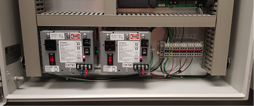
As seen in Figure 1, 24VAC power is normally provided to the HVAC controller using an external step-down transformer. This transformer gets its power from (i.e. has its primary windings attached to) higher line voltages that feed higher power equipment nearby. The most important feature of this transformer is that the supplied 24VAC input power is not full-wave rectified. In a full-wave rectified waveform all the negative voltage of the AC waveform is made positive. Unfortunately, this can cause issues at a system level.
In many cases multiple HVAC controllers are powered within a single control enclosure. The 24VAC power from the transformer can be daisy-chained to each controller power connector. One of the secondary transformer wires are normally connected to the panel ground, which is often electrically the same as the ground plane and/or chassis ground of each controller. When a full-wave device is present on a power network, it can cause a short, as there is a direct path from the non-grounded secondary to the grounded one through the diode of the full wave rectifier bridge. For more information on power supply compatibility see the application note here.
In Part 1 of the series, we discussed the similarities and differences between low cost development boards and production control devices. One criticism against using a low cost single board computer development platform for building automation is that they do not accept 24VAC power using the typical screw type terminal block connectors found on purpose-built control devices. However, designing a 5VDC powered board to run on 24VAC power is an extremely easy thing to do. In the next section, we will understand how we can generate all the necessary voltages for our building automation control system, for both the control board circuitry and the relay signaling, from the 24VAC using the TPS65217C power management integrated circuit (PMIC) that exists within the OSD3358 SiP and some external circuitry.
2.2 Generating Control Board Voltages
The OSD3358 SiP requires a 5 volt direct current (VDC, or just V) input. Therefore, we first need to put external circuitry in place to convert the 24VAC power input to what is required by the SiP as seen in Figure 2. To do this, we will use a switching buck regulator. Switching regulators are excellent for their power efficiency and are useful in cases where the voltage delta between the regulated output and unregulated input is large. The only drawback to these types of regulators is the potential to introduce switching noise into the system. Switching regulators are not well suited for directly supplying noise sensitive analog circuitry. However, this is not an issue in this case as the 5V power output will only be used to power digital circuitry, mainly the OSD3358 SiP.
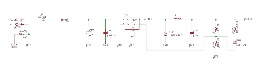
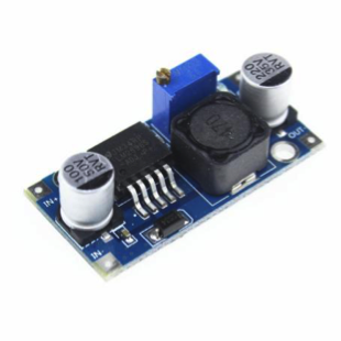
For the reference design, we will be using the popular LM2596 buck regulator. The switching frequency of this regulator is slightly higher than many other offerings, making it easier to filter out noise if that becomes an issue. All that is needed is the addition of a few capacitors and a 330mH or 470mH inductor. The 5V fixed output version instead of the configurable output version of this regulator may also be used, if desired. Using the fixed output version would remove the feedback resistors, R165 and R166, seen in Figure 2. Additionally, when looking to prototype your system, a complete adjustable regulator board can be found online for only a few dollars each, see Figure 3.
One of the nice features of the OSD3358 SiP is that the internal PMIC has both 3.3V and 1.8V output power rails that can be used for other components in the HVAC controller. This includes all of the digital logic as well as the analog circuits. These output power rails are generated using linear dropout (LDO) regulators. While LDOs are a little less efficient, they do not have the switching noise associated with other types of regulators. Therefore, we can use these output power rails for all other components in our controller.
2.3 Generating Relay Voltages
In addition to the voltages needed on the control board, the 24VAC input power is used to generate 24VDC power which is used by the relays and Universal Inputs on the HVAC controller. In the reference design, this is accomplished using a the ST L7824, which is 24VDC linear regulator, as seen in Figure 4.
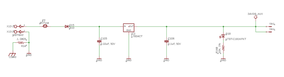
This regulator can provide up to 300mA of current at 24VDC which is perfect to completely power all the auxiliary devices on the board. Each relay requires 15mA of current while each Universal Input can supply up to 20mA of current to a remote sensor device when configured as a 4mA to 20mA loop powered sensor. Additionally, there are many similar regulators if this device is not available or you need a different amount of current to support the relays and Universal Inputs in your system.
Linear regulators are the most efficient when the output voltage is very near the unregulated input voltage. However, we must ensure that the unregulated input does not go below the regulator’s dropout voltage. The dropout voltage is usually one or two volts greater than the regulated output. Therefore, we will need a reasonably large filtering capacitor that can charge quickly and provide the required current during the negative cycle without dipping below the regulator’s dropout voltage. Additionally, the peak voltage on the positive cycle for 24VAC half-rectified input will be approximately 33V. Hence, a 50V rated capacitor of 1000µF (microfarad) or greater is usually adequate to ensure that the unregulated voltage does not dip below dropout at full device current load (not shown in Figure 4). A great application note regarding building automation power supply schemes can be found here
2.4 Importance of Capacitor Choice
Another important consideration is the lifespan of the building automation control system. Building control devices should be designed to last a minimum of 10 years. In general, devices such as capacitors are the main point of failure in building automation control systems, where as processors, like the OSD3358 SiP, seem to last forever. Therefore, it is important to choose capacitors carefully in order to maximize the life of the design.
Some types of capacitors lose capacitance over time. Therefore, the filter capacitors should be slightly oversized so that we don’t have any issues with input regulation as the capacitors age. A good discussion of capacitor lifespan can be found here.
While capacitors receive the most wear in a HVAC controller, we also need to be careful to protect the other components in order to ensure a robust and long-life system.
3. Board Edge Protective Devices for HVAC Controllers
In order to ensure a minimum 10 year lifespan, it is important to protect and ruggedize the inputs and output of the board. In industrial environments, damage to the HVAC controller can occur from multiple sources: Terminal blocks incorrectly wired by the installer; Power surges from lightning or other electrical disturbances; etc. If not properly protected, this damage can potentially take down the system, endangering property and lives. For example, a lightning strike on the central plant of a hospital could bring down the chiller and boiler plant resulting in the inability to control the environment for the patients.
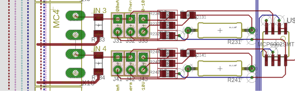
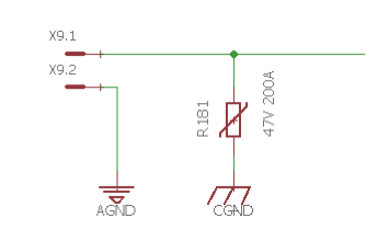
A common way to protect the board inputs and outputs is through Metal Oxide Varistors (MOV), Transient Diodes (TVS), and Fuses. Protection has been added to the reference design. You can see how the Universal Inputs are protected by a varistor in Figure 6.
The only exception is the JTAG connector pads for the OSD3358 SiP which are seldom, if ever, used. Even if the OSD3358 SiP were to be damaged, the whole system will not fail given that protection and isolation on the outputs means that the damage will not be able to be propagate to other components in the system. The following sections will describe the various protection components and where they are used in our reference design.
3.1 Metal Oxide Varistors (MOV)
Metal Oxide Varistors (MOV) are good choices for protecting Universal Inputs. If a voltage above 40V is presented to an input, the current is quickly directed to CGND. A good discussion on MOV selection can be found here. In general, through-hole varistors are capable of absorbing much more energy than surface mount devices.
3.2 Transient Voltage Suppression (TVS)
Transient Voltage Suppression (TVS) diodes. These are good for protecting communication ports from short duration voltage overages that are cause by electrical disturbances. TVS diodes to peripherals such as RS-485 and USB. The RS-485 interface, in particular, must be isolated and protected, as it forms a long distance DC circuit with many other controllers.
3.3 Fuses
Fuses are included where overcurrent is a possibility. In an overcurrent situation, the fuse will trip or fail before the circuit behind the fuse is damaged, like what happens when you plug in too many devices to an outlet in your house. Fuses have been added to the RS-485 port since large induced currents are possible from electrical disturbances due to the long transmission line lengths attached to the port.
4. Concluding Remarks
With the very simple addition of two external regulators and some board input and output protective devices, we transform a miniature personal computer in a package into a rugged embedded industrial control device that is capable of operating in many harsh environments. The OSD335x SiP eliminates the need for many of the required power supply circuits by integrating and encapsulating them into a complete compute system that presents itself as a durable microcontroller-like package. Please join us for the final part of this series where we will tie all of the elements of this series into a single board design and build it.
7 About our Guest Author
This article was guest written by Calvin Slater who is a senior controls engineer that has spent eight years in the Building Automation System Control Industry and is highly interested in embedded hardware as well as open-source building automation frameworks. He is also a contributing editor for AutomatedBuildings.com where he has authored a series of articles on the system edge controller.
8 Revision History
| Revision Number | Revision Date | Changes | Author |
|---|---|---|---|
| 1 | 5/22/2019 | Initial Release | C. Slater |
| Return to “Part 2 : Communications and I/O” | Continue to “Part 4 : Designing for System Deployment” >> |
