Neeraj Dantu
Forum Replies Created
-
AuthorPosts
-
Coder,
The IAA is the industrial temp range version of the BAA. There are no difference in the design between the BAA and IAA. Just the temperature range they operate over. You can use the same file for both parts.
Best,
Neeraj
Gzazo,
Please take a look at our eMMC application note here: https://octavosystems.com/app_notes/designing-for-flexibility-around-emmc/. It described the eMMC specification that is supported. As long as the eMMC adheres to these JEDEC standards, it should work. On initial assessment, the eMMC you linked looks like it will work just fine. Note that it is an eMMC 5.0/5.1 standard and so, special care must be taken while routing the eMMC as described in the application note liked above.
Best,
Neeraj
Hey Manuel,
The SD card could have failed. Can you use a different SD card to see if that works?
If that doesn’t work, the best way to debug this would be to attach a USB to UART connector to the board and look at the console output of the board with the SD card that is failing. Please post some logs if you can.
Best,
Neeraj
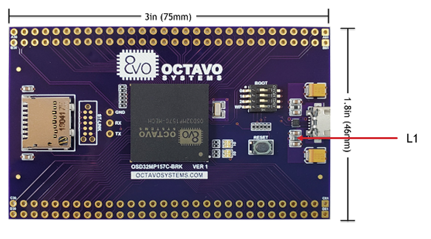
Karl,
The location of L1 is pointed out below. (If the image below is not visible, it is also attached to this reply for download)

Please let us know if you have more questions.
Best,
Neeraj
-
This reply was modified 4 years, 8 months ago by
 Neeraj Dantu.
Attachments:
Ian & Tobias,
We apologize for the delay in getting you a response to this question. Please see below for the requested data for the high speed buses below:
Signal Name Trace Length(um) Differential(um) DSI DSI_D1_N 14889.249 387.191 DSI_D1_P 14502.058 DSI_D0_N 15464.216 927.249 DSI_D0_P 14536.967 DSI_CK_N 15307.686 -410.481 DSI_CK_P 15718.167 USB1 USB1_N 15379.511 559.346 USB1_P 14820.165 USB2 USB2_N 18453.704 572.107 USB2_P 17881.597 Note that all lengths are in microns.
Best,
Neeraj
Samuel,
Please take a look at the Thermal Application note for OSD32MP1 here: https://octavosystems.com/app_notes/osd32mp15x-thermal-guide/
It could help you estimate the case temperature for current dissipation and allow you to decide on your thermal options. Because the PMIC has several rails that are both DC/DC converters and LDOs, there could be variation in terms of heat generation. We recommend you prototype the power draw with a development board and make measurements for temperature to see if the device stays in specification range. Doing this will also allow you to evaluate your heat dissipation options and whether you will need a heat sink.
Best,
Neeraj
Hey Tobias,
The tutorial describes the procedure for OpenST Linux v1.1/1.2. The application note needs to be updated to use v2.0. Until then, we suggest you use v1.2 for your development if you want to follow the application note. You can also make the developer package compile your device tree a different way:
1. Add the target file dtb name to <u-boot directory>/arch/arm/dts/Makefile
2. Add target board name to DEVICE_TREE variable in $PWD/../Makefile.sdk
You should not have to add the target board device tree name to the make command if you do the above.
Best,
Neeraj
Tim,
The only boundary scan capable device within OSD335x is the processor AM335x. The BSDL for the processor is available on the manufacturer’s website(https://www.ti.com/lit/zip/sprm607).
Note that all of the internal connections within the SiP are already validated as part of final test for the device. So, it is not necessary to test them.
Best,
Neeraj
Mario,
If you are interested, the information is just scattered.
1. The datasheet (https://octavosystems.com/docs/osd335x-datasheet/) contains the RTC related circuit configurations in section 7.5.1
2. This forum post has all the information needed on the software side: https://octavosystems.com/forums/topic/osd335x-c-sip-bootloader-issues/
There is also a very helpful guide put together by Aleix: https://docs.google.com/document/d/1mLe8aKckKvg9QwjWJkdTg8gPltMKCRK__lkcNBFa6k0/edit for a software work-around to disable RTC.
We do plan to update the tutorial series with this info, but if you need it, the above links should have you covered.
Best,
Neeraj
Ian,
You don’t have to worry about SiP internals. If you match the trace lengths from the SiP balls to the external devices, you should be able to achieve optimal performance.
Best,
Neeraj
Amin,
Unfortunately, not all of the IO pins of STM32MP1 are exposed on the BRK headers. Specifically, a pin with HSYNC function is not available on the BRK headers. We recommend using a SPI display as an alternative.
If you need to use a big display, please take a look at the Discovery Kit(https://www.st.com/en/evaluation-tools/stm32mp157c-dk2.html)
Best,
Neeraj
hswoo,
Did you set the EEPROM WP pin to GND?
Note that the flashed image would still check for the EEPROM ID. Please take a look at https://octavosystems.com/app_notes/osd335x-eeprom-during-boot/ to resolve the issues with EEPROM ID.
For specific errors, please take a look at the output of the script or post it here to determine what is going wrong.
Best,
Neeraj
Amin,
We assume you are asking about device tree. The sources for the BRK board are available here: https://github.com/octavosystems/osd32mp1-brk-device-tree. Enabling QT using Distrubution Package: https://www.emsyslabs.com/how-to-compile-linux-using-yocto-for-stm32mp1/.
Best,
Neeraj
June 19, 2020 at 2:12 pm in reply to: OSD3358-512M-BSM USB1 gadget problem, when I supply from VIN_USB #10266Jozsef,
A couple of things to note here:
1. Please verify the device tree initialization of USB1 as device: https://github.com/RobertCNelson/dtb-rebuilder/blob/4.14-ti/src/arm/am335x-pocketbeagle-common.dtsi#L981
2. The boot scripts in https://github.com/RobertCNelson/boot-scripts/tree/master/boot are responsible for starting the USB gadget on the interface.
The behavior you are describing with PocketBeagle is odd. For the USB interface to come up in device mode, USB1_VBUS needs to be set to >4.4V. So, powering the PocketBealge with AC input could not have activated the USB port.
On PocketBeagle, by default, USB0 is used in device mode and USB1 is used in host out of the box. If it is possible to change your usage of the ports, you will have support for device and host out of the box.
Best,
Neeraj
Fury,
You should be able to cross compile and update the kernel using the Developer Package: https://wiki.st.com/stm32mpu/wiki/STM32MP1_Developer_Package.
Best,
Neeraj
-
This reply was modified 4 years, 8 months ago by
-
AuthorPosts