OSD32MP15x Thermal Guide
Published On: June, 23, 2020 By: Eshtaartha Basu | Updated: October 26, 2023 by Greg Sheridan
Introduction
The temperature of a device during operation in a system is an important parameter as it affects many properties such as device functionality, reliability and life. Since OSD32MP15x is a System-In-Package (SiP) with several ICs and passive components, single IC package data cannot be used to estimate its thermal characteristics. Hence, it was necessary to characterize OSD32MP15x SiP for its thermal behavior.
This document will provide thermal characteristics of OSD32MP15x and a way to estimate junction temperature. We will also provide typical case temperature values of OSD32MP15x under few common operating conditions.

Table of Contents
Typical Operating Case Temperature
Understanding the typical operating case temperature of OSD32MP15x under different loads in very helpful when it comes to designing cases or enclosures around it.
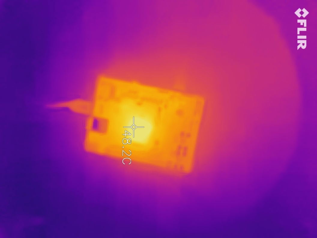
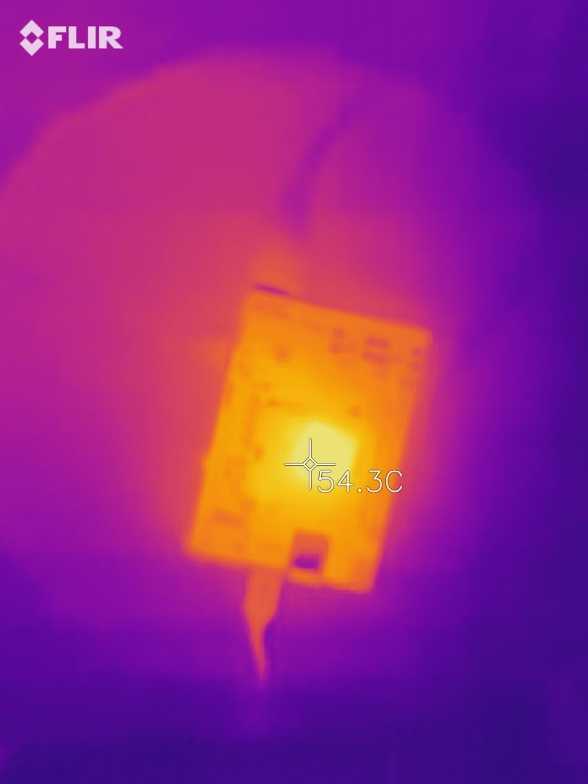
For example, Figure 1 shows case temperature of OSD32MP15x on OSD32MP157C-DK2 board in Linux Idle state. Figure 2 shows case temperature of OSD32MP15x on OSD32MP157C-DK2 board while a video file is being played on an external HDMI monitor. The thermal pictures were captured using FLIR ONE thermal camera. As can be seen, changes in processor load as well as external power load can significantly change the device temperature.
Case Temperature Variation
If we look at the major components within the OS32MP15x, i.e. the STM32MP1 processor, STPMIC1 power management IC, and DDR memory, each has different thermal contributions and requirements. Figure 3 shows the rough component placement within the OSD32MP15x (Note: dot indicates pin A1).
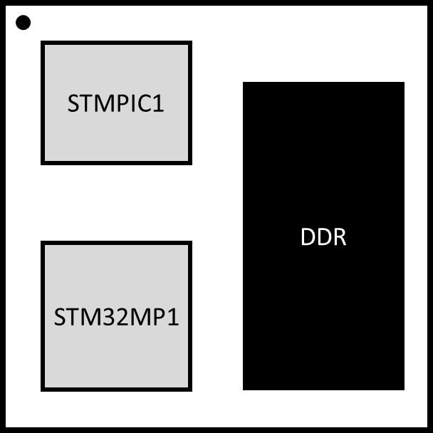
Figure 4 shows the thermal variation across the OSD32MP15x at steady state on the OSD32MP1-BRK when running a light load. As can be seen, the processor is approximately 8 degrees C hotter than the DDR and 3 degrees hotter than the STPMIC1.
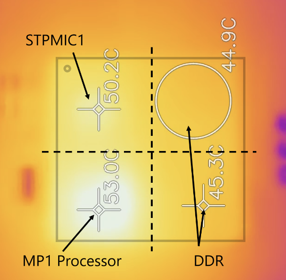
This temperature difference can become more pronounced as the processor load increases. From the respective datasheets, the DDR is the limiting factor from a thermal perspective given that it must maintain a temperature of 0? C to 85? C (commercial) or -40? C to 85? C (industrial). The thermal limits for the OSD32MP15x stated in the datasheet reflect that the DDR must operate within its thermal limits in order to perform reliably. However, as long as the thermal limits for each component are respected, the temperature of the processor and STPMIC1 can run up to the maximum junction temperature as stated in the datasheet for the given part. For example, the processor in the OSD32MP157C corresponds to the Suffix 3 version of the STM32MP157C described in the STM32MP157C/F datasheet.
OSD32MP15x Thermal Parameters
To determine the Thermal Parameters of OSD32MP15x, digital I/O of the OSD32MP15x were use as temperature sensors. Many of the digital I/O of the device behave like a diode when the device is powered off due to the characteristics of the I/O cell. Given that voltage across a diode junction varies with temperature, it is possible to create a junction temperature vs diode junction voltage curve by measuring the diode junction voltage at various temperatures. In a still air chamber, the diode junction voltage was measured by heating the device to known temperatures. Once the temperature vs. diode voltage curve was complete, the OSD32MP15x was powered and run at a moderate load. Once a steady state case temperature was obtained, the device was powered off and the I/O diode junction voltage was immediately measured. The diode junction voltage, case temperature ( ) and power (
 ) used to run the device were all recorded (see procedure in Section 4). Then the corresponding junction temperature (
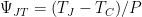
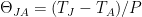
 ) was found using the diode junction voltage and the previously measured junction temperature vs diode junction voltage curve. Finally, the thermal parameters were calculated using the follow formulas:
 ,
,  ,
,  ,
, 
The measured Thermal Parameters of OSD32MP15x are given in Table 1.
| Thermal Parameters | Value (OC/W) |
 | 0.95 |
 | 21.35 |
Table 1 OSD32MP15x Thermal Parameters
(1)  is the measured Thermal Resistance from Junction to Top of Package as measured above the STPMIC1 PMIC when the SiP is mounted on a 6 layer board (OSD32MP157C-DK2 Reference Design Board) in still air and STPMIC1 PMIC under Linux Idle load, and other components operating per spec.
(2)  is the measured Thermal Resistance from Junction to Ambient Air when the SiP is mounted on a 6 layer board (OSD32MP157C-DK2 Reference Design Board) in still air and STPMIC1 PMIC under Moderate load, and other components operating per spec.
Measuring Case Temperature and Estimating Junction Temperature
To measure the case temperature of OSD32MP15x SiP:
- Tools needed:
- Thermocouple (for example, Perfect-Prime TL0225 surface contact, 0.25mm diameter with K-Type Sensor Probe) or
- FLIR ONE PRO Thermal Camera.
- Calibrate thermocouple or other temperature measuring device such as FLIR ONE PRO with known temperatures such as ice-cold water and boiling water.
- Place the SiP in an enclosure so that there are no stray air currents (i.e. still air chamber) while making measurements and run the desired application on it.
- Make contact or fix the thermocouple on the package or focus FLIR ONE PRO on the package. For thermocouples, make sure of good contact with the top surface of the SiP using thermal grease.
- Record the case temperature (
 ) once the temperature is stabilized.
 - Measure the input power () consumed by the SiP.
- Case temperature () thus obtained may be used to verify if the SiP is operating under conditions specified in the datasheet.
It may be desirable to estimate the Junction Temperature () of the STM32MP15x Die inside the System in Package. In this case it can be estimated with the following equation:

Revision History
| Revision Number | Revision Date | Changes | Author |
| 1 | 06/15/2020 | Initial Release | Eshtaartha Basu |
| 2 | 03/01/2021 | Updates for MP1 case temperature variation | Eshtaartha Basu/Erik Welsh |
| 3 | 05/14/2021 | Update on estimating junction temperature | Masood Murtuza Erik Welsh |
