


OSD335x-SM System-in-Package
Smallest AM335x Module, Quickest Design
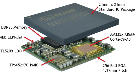
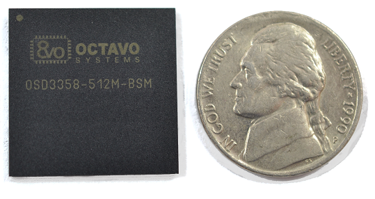
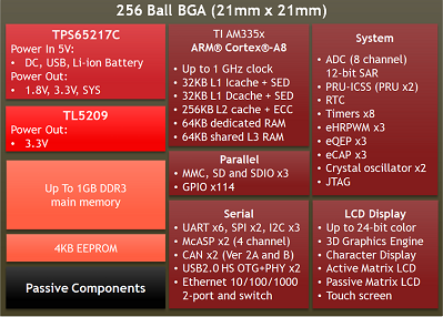
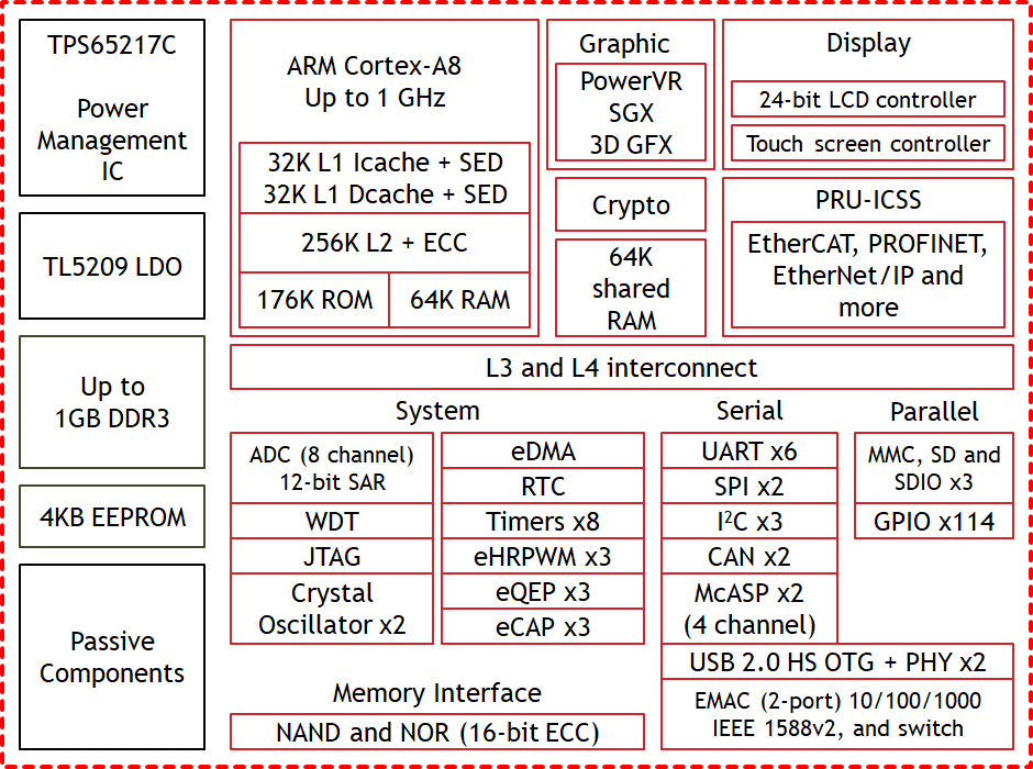
The OSD335x-SM is the smallest Texas Instruments AM335x module. It integrates the TI Sitara™ ARM® Cortex®-A8 AM335x processor, DDR3 memory, TPS65217C PMIC, TL5209 LDO, all the needed passives, and 4KB of EEPROM into a single BGA package. At 21mm X 21mm, it is 60% smaller than the discrete components and 40% smaller than the OSD335x.
The OSD335x-SM utilizes the same wide 1.27mm (50mil) pitch as the rest of the OSD335x family. This combined with a new optimized Pin Map allows designers to escape all the BGA signals in a single layer. The wide pitch also simplifies the assemble process and removes common concerns associated with manufacturing BGAs.
The OSD335x-SM also gives designers the ability to tailor the device to meet their needs. The I/O Voltage Domains and the ADC Ranges are both programmable. The PMIC low power modes are also made accessible as well as the PMIC voltage monitors giving the ability to more finely tune the power performance of the final design.
The OSD335x-SM is the perfect solution for the designer that is looking for the most flexible ARM-based solution in the smallest footprint.
Additional Variants:
OSD335x – Same functionality in a larger package and NO EEPROM.
OSD335x C-SiP – Same functionality adding eMMC Flash, and MEMs Oscillator, in 27mm X 27mm package.

|
|
- OSD335x-SM Layout Guide – Recommendations for laying out and escaping the OSD335x-SM device
- OSD335x Schematic Checklist – Detailed Technical Checklist to Help Users Review OSD335x-BAS/IND or OSD335x-BSM/ISM designs
- OSD335x-SM Tutorial Series – A series of documents that gives you detailed information on how to design with the OSD335x-SM
- OSD335x Family Pin Assignments – A Guide that lists and compares the pin mappings of the OSD335x devices to the AM335x
- OSD335x-SM Power Application Note – An application note for understanding the power system and power budgeting for the OSD335x-SM.
- OSD335x-SM Thermal Management – An Application Note outlining the Thermal Performance and Key Thermal Parameters of the OSD335x-SM.
- OSD335x EEPROM During Boot – Techniques to program an EEPROM with a unique code, a board ID, to configure your Linux image during boot.
- HVAC Controller Design Using AM335x Based System in Package – A Four Part Series outlining a Reference Design for HVAC or Other System Controllers
- OSD335x BAS/IND to OSD335x-SM Migration Guide – Detailed guide to help migrate a a OSD335x-BAS/IND design to the smaller, easier to use OSD335x-SM
| Product Number | Description | Price | Order From |
|---|---|---|---|
| OSD3358-512M-BSM | System-In-Package - AM3358, 512MB DDR3L, 4KB EEPROM, TPS65217C, TL5209, Passives - 21mm X 21mm, 256 Ball BGA, 0°C to 85°C | Contact Sales | Digi-Key Mouser Arrow Avnet Request a Quote |
| OSD3358-512M-ISM | System-In-Package - AM3358, 512MB DDR3L, 4KB EEPROM, TPS65217C, TL5209, Passives - 21mm X 21mm, 256 Ball BGA, -40°C to 85°C | Contact Sales | Digi-Key Mouser Arrow Avnet Request a Quote |
| OSD3358-1G-ISM | System-In-Package - AM3358, 1GB DDR3L, 4KB EEPROM, TPS65217C, TL5209, Passives - 21mm X 21mm, 256 Ball BGA, -40°C to 85°C | Contact Sales | Digi-Key Mouser Arrow Avnet Request a Quote |
Reference, Evaluation, Development Platform
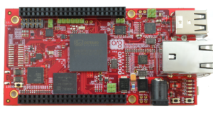 The Octavo Systems OSD3358-SM-RED platform is the official Reference, Evaluation, and Development board for the OSD335x-SM family of devices. It was developed to allow designers to quickly evaluate the OSD335x-SM in their application. It has many common interfaces and sensors. It also has a pair of expansion headers that are compatible with BeagleBone® Black Capes. This provides a platform to quickly prototype different applications.
All of the design resources and software are opensource making it an ideal known good starting point for new designs.
Other Development Boards
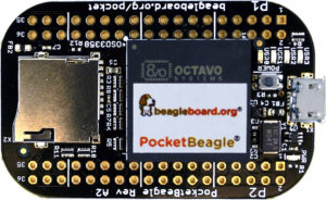 The PocketBeagle®, from BeagleBoard.org®, is a low cost, bare bones prototyping platform. It consists of the OSD3358-512M-BSM, microSD card holder, microUSB connector, and 72 header pins. The header pins expose many signals that can be used to construct a lager system, like GPIO, PWMs, ADC inputs, USB, and PRU I/O. At 56mm x 35mm x 5mm, PocketBeagle® is the smallest development platform for the OSD335x-SM products.
Like all of the BeagleBoard.org products, all of the design files and software are completely opensource and available on their website.
Symbols
To make designing with Octavo Systems devices easier, a number of schematic symbol libraries have been provided below. There are options for a variety of schematic capture and layout programs. Please choose the one that best suits your needs.
Looking for symbols for a different CAD tool or 3D models? Visit SnapEDA for an extensive collection of symbols and foot prints for different CAD programs as well as 3D Step models. (Please make sure you select the correct version of the OSD335x family in the selector box in the top left corner.)
Software
Provided below is a copy of the DDR3 calibration program that is provided from Texas Instruments. It has been provided here for your convenience.
Building Automation System Controller
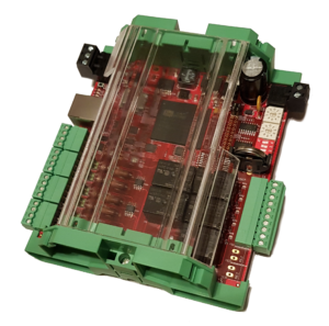 The Building Automation System Controller reference design was developed as a flexible, multi-purpose freely programmable embedded system that can be found in a variety of HVAC, lighting, and security applications. Using the OSD3358-SM-RED as a starting point the design also features:
- A fully isolated RS-485 transceiver
- a CAN bus transceiver
- 6x Analog Universal Input Modules supporting Thermistor/Dry Contact, Pulse, 4-20mA, and 0-10VDC industry standard input signals
- 5x 10 A Form A relay outputs
- Dual Rotary decimal encoder switches
- 1x four-position dip switch
- Battery back up for Hibernation/RTC support.
This design is a great starting point for anybody looking monitor and control a chiller, boiler, pumps, valves, fans, lights, indoor air quality, or electric metering, occupancy detection, and access control for industrial applications. This reference design was designed as part of a 4 part series on Building Automation Controllers, developed by a Senior Controls Engineer, Calvin Slater.
Note: The version of Building Automation System Controller using the OSD3358-512M-ISM has not actually been built. It is provided as reference only.

 Download Latest Reference Design Files
FAQs
In our lab, we have used both the XDS110 and XDS200 emulators. Depending on your emulation / debug needs, you can also use higher end emulators like the XDS560v2.
If you plan to use debug features like trace that are available on higher end emulators, please make sure that you bring the EMU2/EMU3/EMU4 pins to the JTAG header. If you do not plan to use those higher end debug features, then those particular EMU signals do not need to be routed to the JTAG header.
Texas Instruments also provides a number of different websites detailing information about the emulators that can be use with the AM335x processor, and thus the OSD335x SiP, as well as general inofrmaton about JTAG connectors and adapters:
direct linkLinux images from Bealgeboard.org require EEPROM to be programmed with a board ID. The following solutions can be used to overcome this issue:
1. Bypass the checks in the bootloader (u-boot)
2. Use Robert Nelson’s patch to create u-boot that will boot and allow you to program the EEPROM: In u-boot apply the patch:
u-boot also uses a device tree that you might need to modify. You should find the u-boot device tress in ./arch/arm/dts It is useful to look through the 0001-am335x_evm-uEnv.txt-bootz-n-fixes.patch patch from Robert Nelson (see https://eewiki.net/display/linuxonarm/BeagleBone+Black) since this patch modifies device trees and can point you to important directories in u-boot.
A more detailed explanation of the above options can be found in this forum post.
direct link
Generally, XDS200 connectivity issues can be resolved by updating its firmware.
To update a XDS200-class JTAG debugger connected via USB, using a Windows host is highly recommended. Close any instances of CCS that are running in your system. Open a Windows Command Prompt and issue the following commands:
1. Go to the directory where the utility is installed:
- C:\>cd C:\ti\ccsv6\ccs_base\common\uscif\xds2xx
2. Run the configuration just to make sure a XDS200-class debugger is connected and to confirm the firmware revision installed on it:
- C:\ti\ccsv6\ccs_base\common\uscif\xds2xx>xds2xx_conf get xds2xxu 0
3. If you have a single XDS200 connected via USB:
Run the following commands in the exact order shown below (the batch file update_xds2xx does this in reverse order, increasing the chances of failure):
- C:\ti\ccsv6\ccs_base\common\uscif\xds2xx>xds2xx_conf update xds2xxu 0 xds200_firmware_v1008.bin
- C:\ti\ccsv6\ccs_base\common\uscif\xds2xx>xds2xx_conf program xds2xxu 0 xds200_cpld_v1008.xsvf
- C:\ti\ccsv6\ccs_base\common\uscif\xds2xx>xds2xx_conf boot xds2xxu 0
4. After that, run the command in step 2 again to check if the correct firmware was loaded.
- C:\ti\ccsv6\ccs_base\common\uscif\xds2xx>xds2xx_conf get xds2xxu 0
If connectivity issues persist, please go through the XDS200 Wiki to find out more information.
Power consumption of OSD335x-SM depends highly on usage scenarios. The OSD335x-SM Power Application Note and the OSD335x Power Management Software Control Application Note will give you detailed information about OSD335x-SM power consumption in various operating states.
Other helpful resources are:
- AM335x Power Consumption Summary: This wiki page provides current and power measurements for common system application usage scenarios. However, these measurements were made for a presently unsupported version of SDK. Updated power consumption data can be found here.
- Power Estimation Tool: This entails modifying and submitting a spreadsheet specifying processor mode and peripheral usage of AM335x. Login to TI website is required and the results will be emailed to the email address used to login.
All the peripherals supported by the AM335x are also supported by the OSD335x-SM. Please refer to the Ball Map section of the OSD335x-SM datasheet to understand naming conventions of various balls of OSD335x-SM. Also, the OSD335x Family Pin Assignments page gives you detailed information about pin mapping differences between OSD335x-SM and AM335x.
direct linkNo, you don’t. The AM335x die in the OSD335x-SM is the same as the Die in the discrete TI device. This means that the Pin MUX will work the same on the OSD335x-SM as it would on the discrete version. There are differences in the location and position of the signals, however. Please refer to OSD335x Family Pin Assignments page for ball map differences between OSD335x-SM and AM335x.
direct linkYes, OSD335x family runs all Linux distributions supported by TI for AM335x. It is also officially BeagleBoard Compatible so it will run the same Linux distributions found on Beaglebone Family of products.
direct linkThese power pins are driven by the TPS65217C PMIC and are used internally to power the AM335x, DDR and other components. These pins are all connected within the SiP and should not be connected externally. Optionally, these pins can be brought out as test points for debugging purposes only. They should NEVER be used to power external components.
direct link