OSDZU3 Vitis Tutorial
Published On: January, 16, 2023 By: Eshtaartha Basu | Updated: September 18, 2023 by Greg Sheridan
This tutorial will walk you through creating various simple software applications in Vitis 2021.2 for a OSDZU3 System-in-Package based design. It will use the OSDZU3-REF platform as an example.
Here is a video that walk through this guide that you can follow along with!
Objectives
At the end of this tutorial, you will be able to:
- Create a simple “Hello World” software application in Vitis and run it on the OSDZU3 based board (OSDZU3-REF)
- Create various application software in Vitis to test several interfaces on the OSDZU3 based board (OSDZU3-REF)
- Boot the OSDZU3 based board (OSDZU3-REF) from the microSD card
Table of Contents
Prerequisites
This app note assumes you’ve already gone through OSDZU3 Vivado Tutorial and have successfully generated a Vivado Hardware Platform file (.xsa). This hardware platform will be used as foundation for all the software applications created moving forward.
Tutorial Requirements
This tutorial will require the following software and hardware setups.
Software
The software requirements for this tutorial are:
- Xilinx Vitis v2021.2 (Xilinx account and licenses may be required)
- When running the installer, ensure the Install Cable Drivers option is enabled
- Ensure this Xilinx patch is applied to your Vitis installation before proceeding further with this app note: https://support.xilinx.com/s/article/76960?language=en_US
- Vivado Hardware Platform file (.xsa) created using OSDZU3-REF Vivado Tutorial
- Sample Code Files
- Putty terminal program
Hardware
The hardware setup for this tutorial is:
- PC with 4 GB RAM and 1 GB virtual memory (recommended)
- OSDZU3-REF board
- 12V power supply (provided with OSDZU3-REF board)
- Blank uSD card
- USB A-micro-B cables (2)
Creating and running Hello World application
Generating Vitis Platform Project
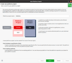
Prior to generating/creating any software application, a Vitis Platform Project (that includes a BSP) must be generated for the hardware platform. The Platform Project will assemble and compile various drivers that relate to the peripherals in the hardware platform for later use in our applications.
- Open Vitis -> choose suitable workspace
- File -> New -> Platform Project -> Give the name as OSDZU3x -> Next

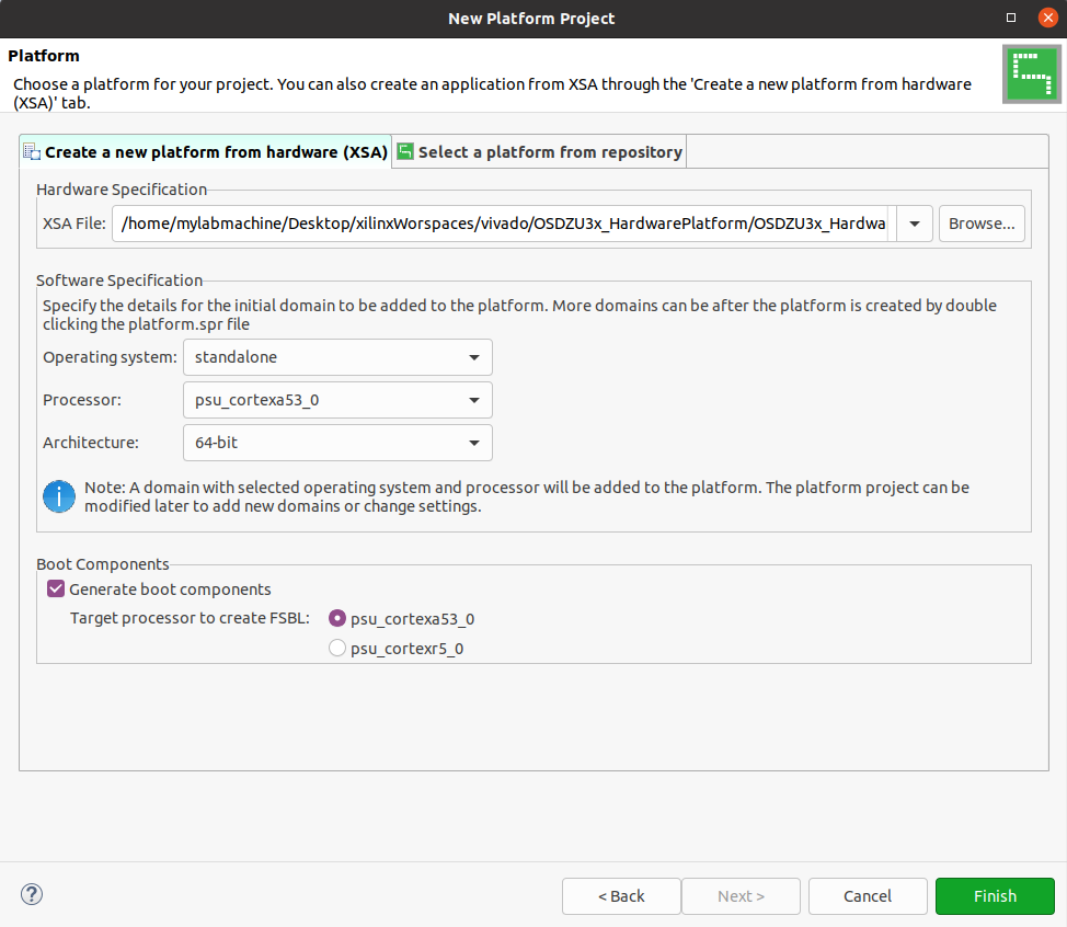
Create Hardware Platform - Choose the location of your XSA file


Choose Location of XSA - Click Finish
- File -> New -> Platform Project -> Give the name as OSDZU3x -> Next
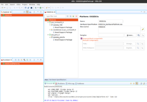
- Right click on OSDZU3x platform under Explorer window -> Build
- Once the Build finishes, under OSDZU3x platform
- Choose Board Support Package -> Modify BSP Setting.

Select Board Support Package - Under standalone, ensure both stdin and stdout are set to psu_uart_0 as shown below
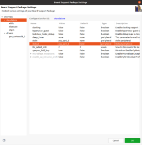

Ensure stdin and stdout are set
- Choose Board Support Package -> Modify BSP Setting.


Creating a “Hello World” Software Project
Now that the Vitis Platform Project is generated, we can begin creating software applications. We will start by creating a simple Hello World application so that you can become familiar with the Vitis flow.
- From the Vitis toolbar, select File > New > Application Project
- When the New Application Project dialog box appears, click Next
- The Platform window lets you choose an existing platform or create new one. Choose the platform already created as part of previous section.
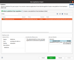

Choose Existing Project - In the Application Project Details window, set the Project name to Hello_OSDZU3x. All settings can be left as defaults.
- The Domain window lets you choose the domain for the application project. Leave the default choice as is and click Next.
- When the following dialog box appears, click on the Hello World under the Available Templates and then click on Finish to continue.
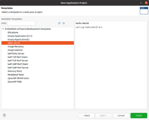

Select Hello World Template - The Hello_OSDZU3x software project will be added to the workspace as shown in the following figure.

Hello_OSDZU3x Added to Workspace - Right click on Hello_OSDZU3x project > Build Project.


Board and JTAG Setup
Please perform the following steps to setup the OSDZU3-REF board and host PC:
- Power up the OSDZU3-REF board using steps from Powering the OSDZU3-REF section of OSDZU3-REF Getting Started Guide
- Setup a successful JTAG connection between the board and Vitis running on PC using steps from JTAG section of OSDZU3-REF Getting Started Guide
- Setup a successful UART console using steps from UART section of OSDZU3-REF Getting Started Guide
Running the Hello World Program on Hardware
In this section, we will be using the SmartLynq JTAG Cable to load the Hello_OSDZU3x.elf executable file into the OSDZU3’s LPDDR4 memory and run it.
From the Vitis GUI Project Explorer, right click on the Hello_OSDZU3x software project and then select Run As > Launch Hardware.
You should see the phrase Hello World being displayed on the serial console window (Putty/TeraTerm/minicom/screen) as show below.

Generating Application Software
Now that a simple Hello World program has been loaded into the LPDDR4 memory and executed, in the next sections will try loading other software applications into the LPDDR4 memory and run them on the board.
Flashing the PS User LED
In this section, we will use a simple software application (provided for you in the Sample Files) to flash the PS user LED on the OSDZU3-REF board.
- Create a baseline application project in Vitis using Hello World template as described in section Creating a “Hello World” Software Project with the following modifications:
- Set the Project name to PS_LED_Blinky
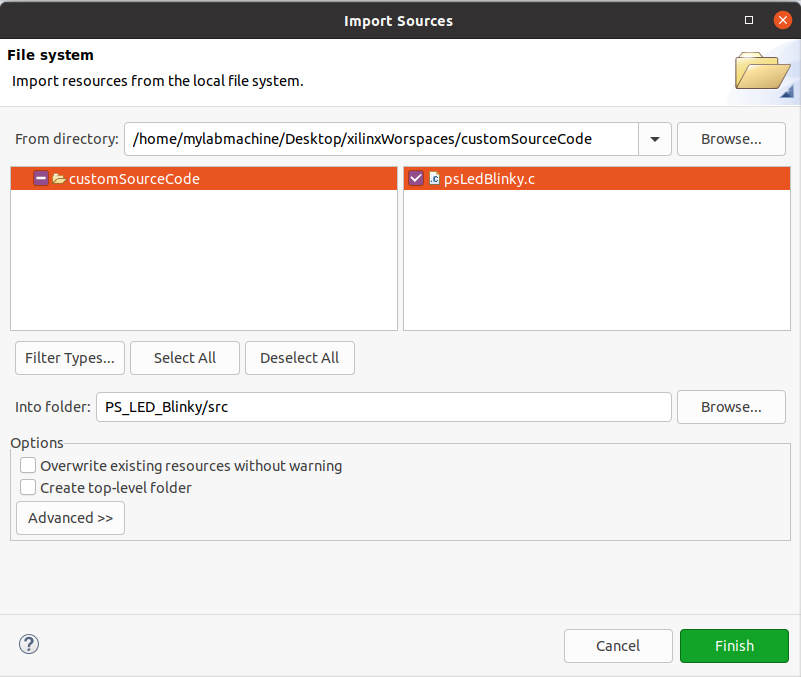
- Right click on the src folder (you would need to expand the PS_LED_Blinky software project to see the src folder) of the PS_LED_Blinky software project > Import Sources.
- Browse for the directory containing the given psLedBlinky.c file (downloaded from the Sample Files) > Open
- Select the file psLedBlinky.c > Finish


Import Sources psLedBlinky
- Right click on the default helloworld.c file > Delete
- The Vitis Project Explorer should now look as shown in the following figure
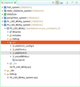

Vitis Project Explorer - Right click on PS_LED_Blinky project > Build Project
- Once the project is built, right click on PS_LED_Blinky project > Run As > Launch Hardware.

The PS_LED_Blinky.elf executable file will be loaded into the LPDDR4 memory and run on the board. LED D6 (PS LED) will start flashing.
Flashing the PL User LED
In this section we will use a simple software application (provided for you in the Sample Files) to flash all the 8 PL user LEDs (D20 – D27) on the OSDZU3-REF board.
- To create and build the PL User LED project, follow the steps already described in section Flashing the PS User LED with the following modifications:
- Set the Project name to PL_LED_Blinky
- Use the given source file c file (downloaded from the Sample Files) instead of psLedBlinky.c
- Once the project is built, right click on PL_LED_Blinky project > Run As > Launch Hardware.
The PL_LED_Blinky.elf executable file will be loaded into the LPDDR4 memory and run on the board. LEDs D20 – D27 (PL LEDs) will start flashing.
Testing the User Switches and Push Buttons
The Vitis Peripheral Tests software template can be used to test the PL DIP Switches (SW5) and Push Buttons (SW1 – SW4).
- Create an application project in Vitis using Peripheral Tests template as described in section Creating a “Hello World” Software Project with the following modifications:
- Set the Project name to periphTest
- Choose Peripheral Tests in Templates window instead of Hello World
- Right click on periphTest project > Build Project
- Once the project is built:
- Set the DIP Switches 8 and 1 of SW5 to HIGH
- Press and hold SW3
- Right click on periphTest project > Run As > Launch Hardware.
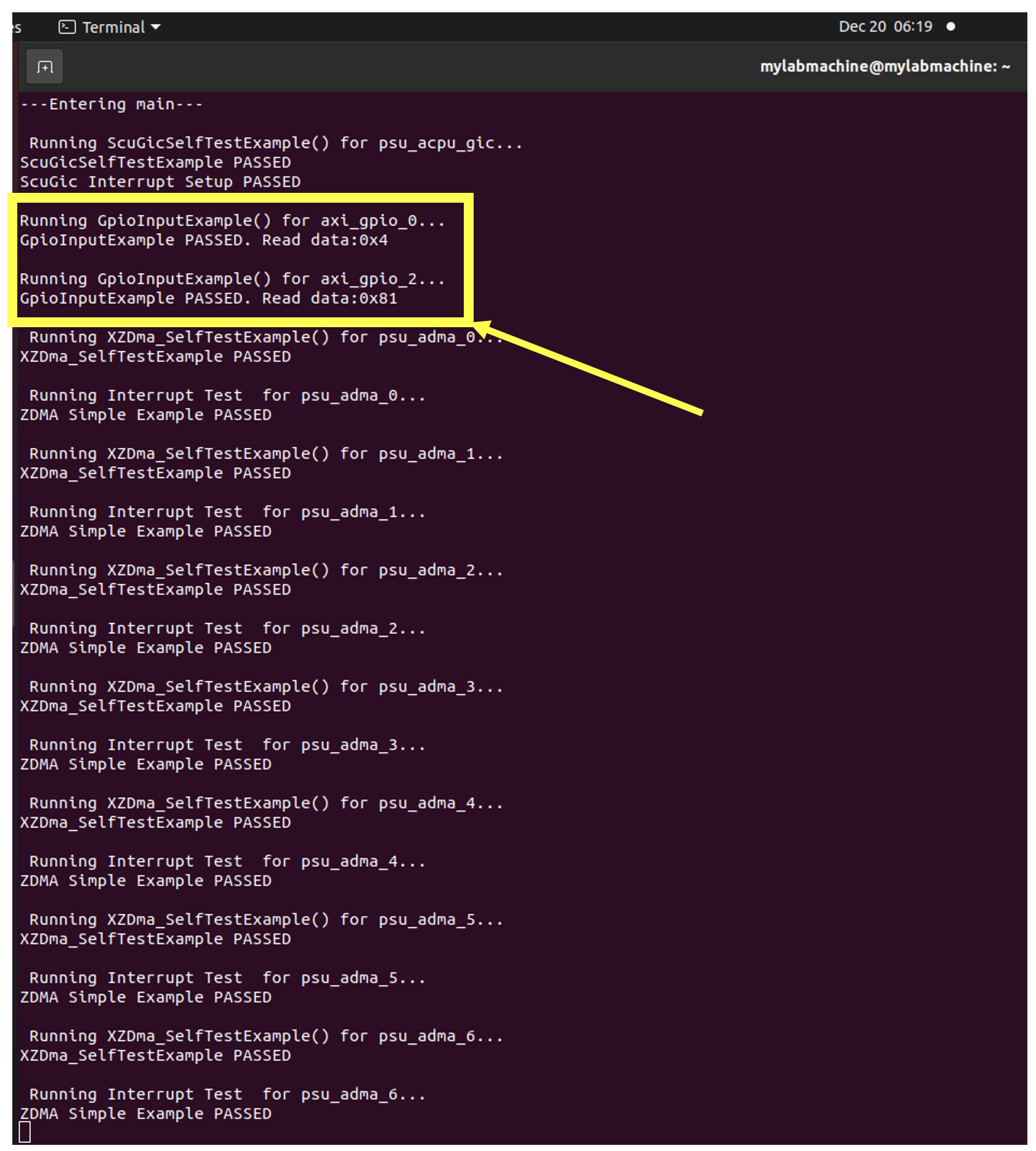
Once the hardware is launched, in order to test the User Switches and Push Buttons connected to the PL, the PL will be configured first. Once the PL is configured, the Periph_Test.elf file will be loaded into the LPDDR4 memory and run on the board.
Once the program starts running on the OSDZU3-REF board, you should see the following read data (highlighted) on the serial console. Read data under axi_gpio_0 corresponds to the status of push buttons. Read data under axi_gpio_1 corresponds to the status of DIP switches.
You can modify the status of push buttons and DIP switches few more times, relaunch the hardware each time and verify if the status of buttons and switches are being read properly.
Gigabit Ethernet Port Test
The Vitis lwIP Echo Server software template can be used to test the Gigabit Ethernet Port.
- From the Vitis toolbar, select File > New > Application Project
- When the New Application Project dialog box appears, click Next
- The Platform window lets you choose an existing platform or create new one. Choose the platform already created as part of previous section.

Echo Server Application Project - In the Application Project Details window, set the Project name to Eth_Test. All settings can be left as defaults.
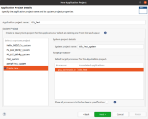
Application Project Detail - The Domain window lets you choose the domain for the application project. Choose Create New.
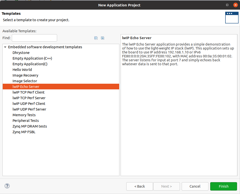
- When the following dialog box appears, click on the lwIP Echo Server under the Available Templates and then click on Finish to continue. The Eth_Test software project will be added to the workspace.


Select IwIP Echo Server Template - From the Vitis GUI Project Explorer, right click on the Eth_Test software project and then select Run As > Launch Hardware.
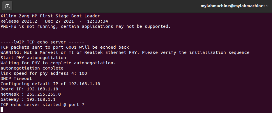
- Wait until the lwIP Echo Server output is displayed on the serial console as shown in the following figure. At this time, the Ethernet port has gone through the auto-negotiation and is ready for normal operation.
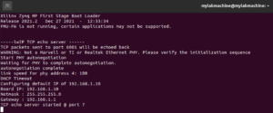

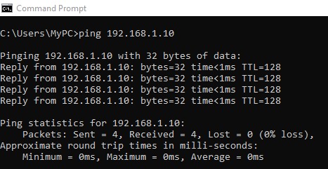
Echo Server Started - Open a cmd window on host Windows PC and ping the board using the board IP address of 192.168.1.10 as shown below. You should see 4 replies back as shown.
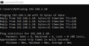

Ping Test from Host PC - To connect to the echo server, use the telnet utility program. Type the following telnet command as shown below and hit the return key.
telnet 192.168.1.10 7
- If the echo server works properly, any data sent to the board is echoed in response. Type a few characters and see them echoed back on the terminal ass shown below.
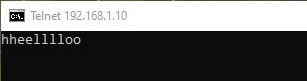

Echo Server Output


Ethernet connection troubleshooting tips
- Ping doesn’t work: If you can’t ping the board from the cmd window of your Windows Host PC, the following troubleshooting steps could help resolve the issue:
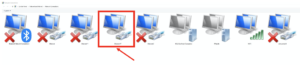
- Locate the network adapter for your board (Ethernet 17 in our case, may be slightly different on your PC) under Network Connections of your Windows Host PC as shown below.

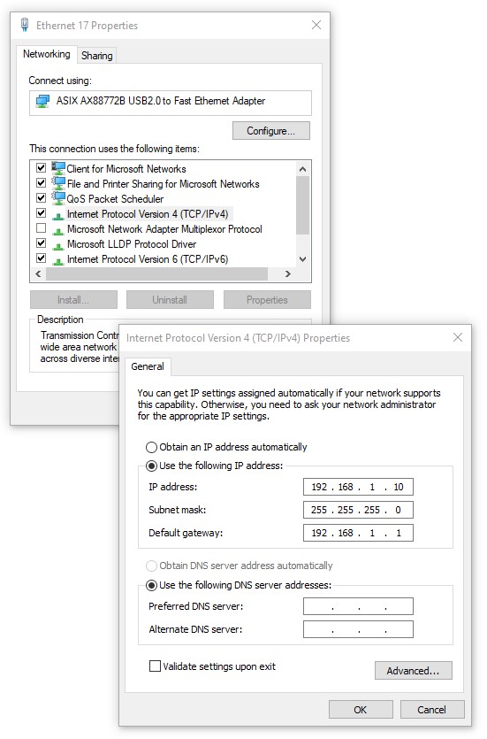
Select Network Connections - Manually configure the IP address as shown below.
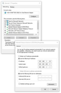

Manually Configure Network
- Locate the network adapter for your board (Ethernet 17 in our case, may be slightly different on your PC) under Network Connections of your Windows Host PC as shown below.
- Telnet not found: Telnet utility is not enabled by default in Windows. You may have to manually enable it using Turn Windows features on or off before using it under cmd window as shown below.
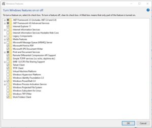

Turn Windows Features On or Off

Booting From Primary/Secondary Boot Devices
In the previous sections, the Vitis debugger was used to load user executables into the OSDZU3-REF board’s LPDDR4 memory over the SmartLynq JTAG cable and run the programs on the board. This method of operation is ideal for debug environment. However, in normal operation user code and bitstream are loaded into the OSDZU3-REF board’s LPDDR4 and Zynq UltraScale+ via on-board primary/secondary boot devices such the microSD Card, QSPI Flash and the eMMC Flash. In the following sections we will show you how to:
- Generate boot image for each boot device
- Program the image into the boot device
- Boot from each boot device
Generating the First Stage Boot Loader (FSBL)
In order to boot from any of the boot devices, a bootloader is required to load the user executable and bitstream into the OSDZU3-REF board’s LPDDR4 and the Zynq UltraScale+ PL. When the Zynq UltraScale+ initially boots, its internal ROM loads the bootloader (FSBL) from the external boot device into the Zynq UltraScale+ internal SRAM and releases the control to the FSBL.
FSBL will then load the user executable from the external boot device into the OSDZU3-REF board’s LPDDR4, loads the bitstream from the external boot device into the Zynq UltraScale+ PL, and then releases the control to the user executable. The following steps describe how to generate the FSBL.
- From the Vitis toolbar, select File > New > Application Project
- When the New Application Project dialog box appears, click Next
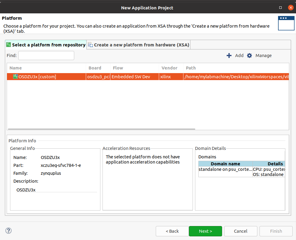
- The Platform window lets you choose an existing platform or create new one. Choose the platform already created as part of previous section.

Choose the already created platform - In the Application Project Details window, set the Project name to fsbl. All settings can be left as defaults.
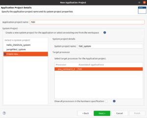
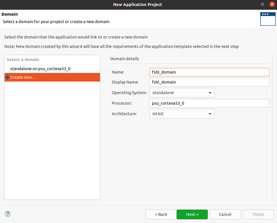
Application Project Details - The Domain window lets you choose the domain for the application project. Choose Create New. Set domain name and other parameters as shown in figure below.

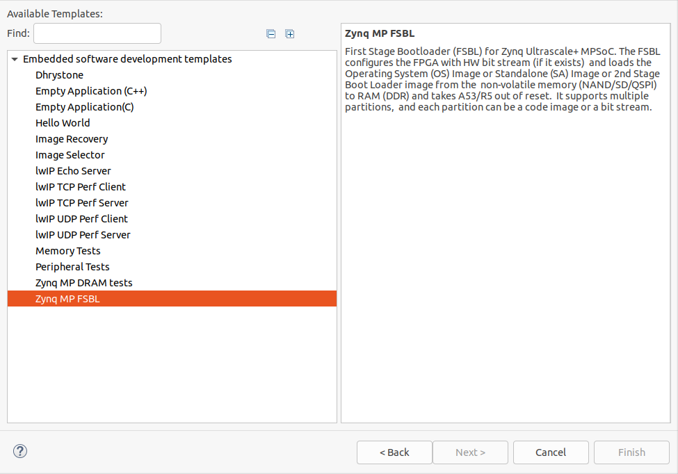
Domain Window - When the following dialog box appears, click on the Zynq MP FSBL under the Available Templates and then click on Finish to continue. The fsbl software project will be added to the workspace. Right click on the project > Build.
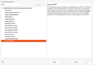

Select Zynq MP FSBL

Booting from the microSD Card
In order to boot from the microSD card, the boot image must be generated and stored on the microSD card.
Generating the SD Card Boot Image
- From the Vitis GUI, select Xilinx Tools > Create Boot Image
- When the Create Boot Image dialog box appears:
- Set the Architecture to Zynq MP.
- Make sure the Create new BIF file radio button is selected.
- Create a folder on Host PC labeled bin_and_mcs_generation
- Click on Browse next to the Output BIF file path to continue as show below.
- Browse to the bin_and_mcs_generation folder and set the BIF file name to output_sd as shown in the following figure. Click on Save to continue.
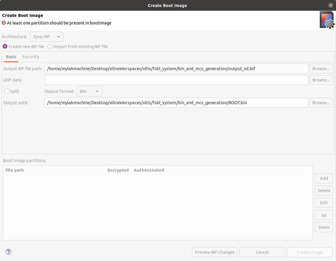
- The Create Boot Image dialog box will look as shown in the following figure. The BIN Output format is specified by default as shown (this format is needed when creating a boot image for the SD card). The name of the output file must be BOOT.bin as shown.
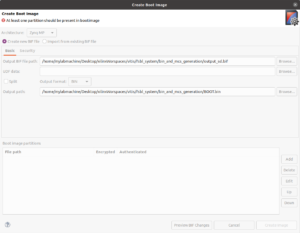

Create Boot Image Dialog
- In the Create Boot Image dialog box, click on Add to start adding Boot Partitions to the boot image.
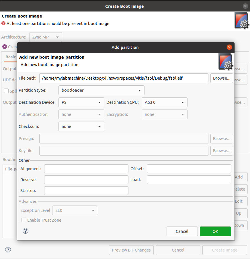
- The first partition to be added to the Boot Image will be the FSBL.
- Click on the Browse button and point to the fsbl.elf file located in the <Vitis_Workspace>\fsbl\Debug folder as shown in the following figure.
- Keep all other default settings as shown below and click OK to continue.
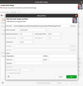

Creating Boot Partition - The FSBL partition will be added to the boot image
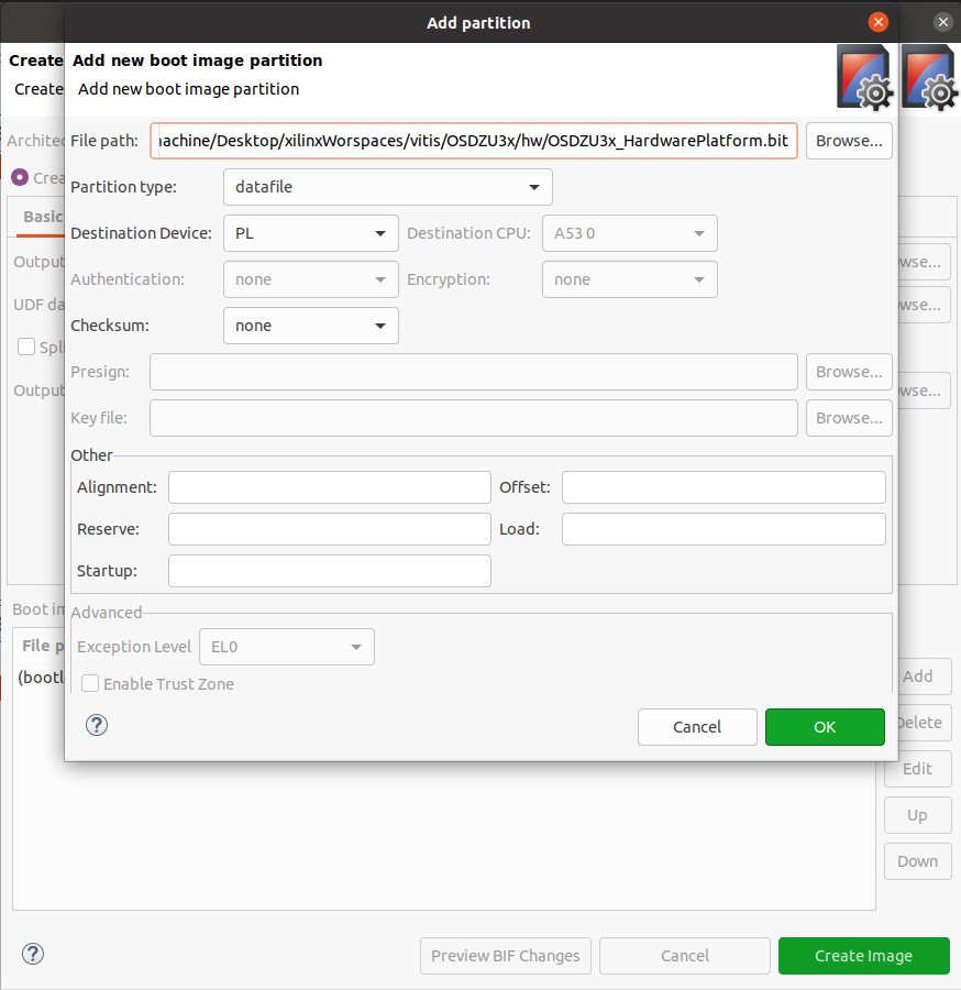
- The next partition to be added is the design bitstream.
- In the Create Boot Image dialog box, click on Add to add the bitstream to the boot image.
- In the Add Partition dialog box, browse to the <Vitis_Workspace>\OSDZU3x\hw\OSDZU3x_HardwarePlatform folder and double click on the OSDZU3x_HardwarePlatform.bit file.
- Keep all other default settings as shown in the following figure.
- Click OK to continue.


Adding the Second Partition
- The next partition to be added is the design application software.
- In the Create Boot Image dialog box, click on Add to add the application software to the boot image.
- In the Add Partition dialog box, browse to the <Vitis_Workspace>\Hello_OSDZU3x\Debug folder and double click on the Hello_OSDZU3x.elf file.
- Keep all other default settings as shown in the following figure.
- Click OK to continue.
- The first partition to be added to the Boot Image will be the FSBL.
The Create Boot Image dialog box should look as shown in the following figure. Click on Create Image to create the SD card boot image.
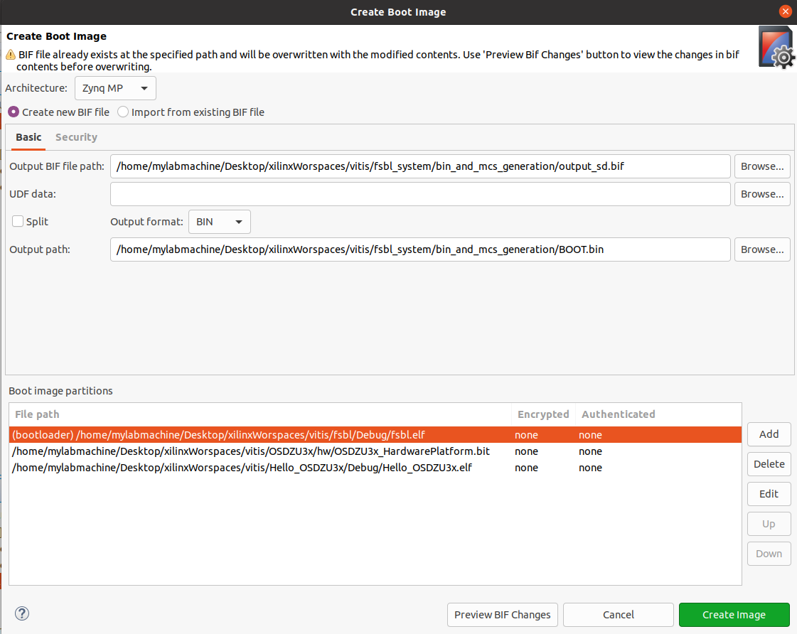
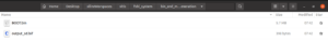
The BOOT.BIN and output.BIF files will be generated in the bin_and_mcs_generation folder as shown in the following figure.

Copying the SD Card Boot Image onto the microSD Card
Using your PC’s memory card reader slot, copy the BOOT.BIN file generated in the previous step onto the root directly of the microSD card (you can also use a USB memory card reader adapter, if your PC does not have a microSD card reader slot). Remove the microSD card from the card reader.
Booting the Board Using the microSD Card
- Power up the OSDZU3-REF board with UART console enabled using steps from UART section of OSDZU3-REF Getting Started Guide
- Once powered, the board will boot from the uSD card and you will see the following on your serial console.
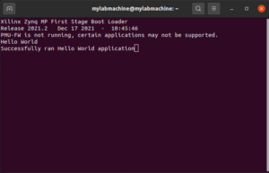

Hello World Example

Revision History
We will continue to update this application note to provide more information and more examples. Sign up below to be notified when we update this guide.
"*" indicates required fields
| Revision Number | Revision Date | Changes | Author |
| 1 | 12/20/2022 | Initial Revision | Eshtaartha Basu |
