OSDZU3-REF Getting Started Guide
Published On: January, 16, 2023 By: Eshtaartha Basu | Updated: September 18, 2023 by Greg Sheridan
Welcome to the OSDZU3-REF, a full featured development platform for the OSDZU3 System in Package. It provides access to most the commonly used peripherals on the OSDZU3. It also provides options for easy expandability through industry standard interfaces. This application note will walk you through the process of getting up and running with the OSDZU3-REF so you can quickly begin developing and prototyping your application.
This application note will be updated as the platform matures. Make sure you stay up to date on the latest by signing up for updates below.
"*" indicates required fields
Table of Contents
Tutorial Requirements
This tutorial may require the following software and hardware setup for some of the use cases.
Software
- To establish JTAG connection over Vivado as described under “JTAG” section below, install Vivado:
- AMD Vivado v2021.2 (AMD account and licenses may be required)
- When running the installer, ensure the Install Cable Drivers option is enabled.
- Ensure this AMD patch is applied to your Vivado installation before proceeding further with this app note: https://support.xilinx.com/s/article/76960?language=en_US
- To establish JTAG connection over Vitis as described under “JTAG” section below, install Vitis:
- AMD Vitis v2021.2 (AMD account and licenses may be required)
- When running the installer, ensure the Install Cable Drivers option is enabled
- Ensure this AMD patch is applied to your Vitis installation before proceeding further with this app note: https://support.xilinx.com/s/article/76960?language=en_US
Hardware
The following additional hardware (not included in the box) have been used in this tutorial:
- Hiearcool USB-C Hub (Model No. UCN3286) –
https://www.amazon.com/dp/B07WPTG7NX?ref_=cm_sw_r_cp_ud_dp_1CVA6KHABBC0BGCB5ZYH - Logitech MK335 Keyboard and Mouse Combo with USB-A type Unifying Receiver – https://www.amazon.com/dp/B072JX77X6?ref_=cm_sw_r_cp_ud_dp_44DXSH7HX9A4AA76K07R
- Dell S3222HN 32-inch FHD External Monitor –
https://www.amazon.com/dp/B09QNPDHD2?ref_=cm_sw_r_cp_ud_dp_GDKZCB64AZA7D7WA5TVD
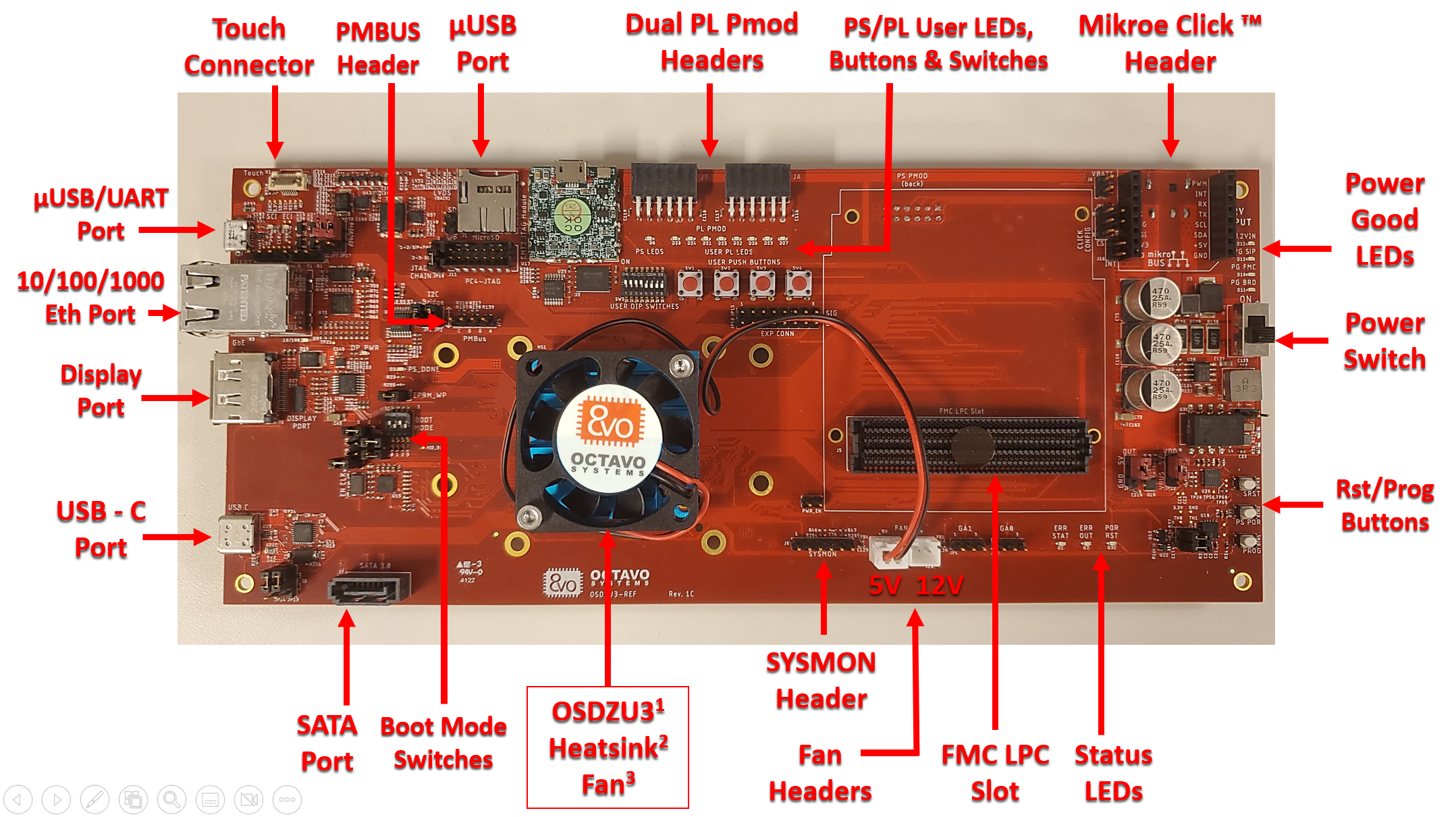
OSDZU3-REF Platform Overview
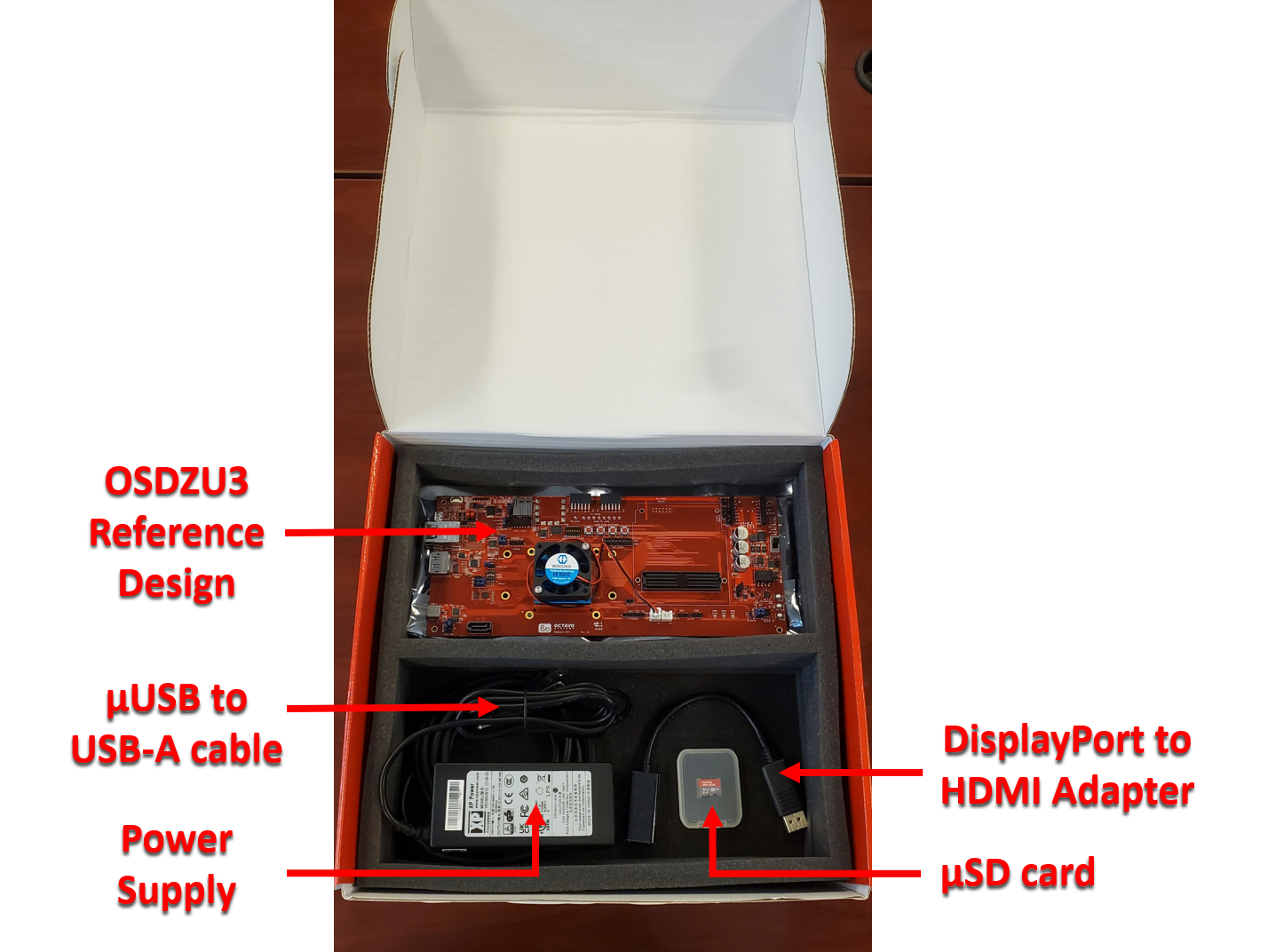
The OSDZU3-REF platform package includes the OSDZU3-REF platform itself as well as a 12V Power Supply, Display Port to HDMI adapter, µUSB to USB-A cable and a µSD card preloaded with the Octavo Systems Petalinux Distribution.
Features Walk Through
The video below will walk you through the OSDZU3-REF features and peripherals. It closely follows the steps outlined in this guide.
The completely Opensource OSDZU3-REF platform features:
| 
|
Full schematics, layout, and other design files for the OSDZU3-REF can be found here.

The initial build of OSDZU3-REF boards uses ES parts. See ES Errata for more information on special considerations.
OSDZU3-REF Boot Options
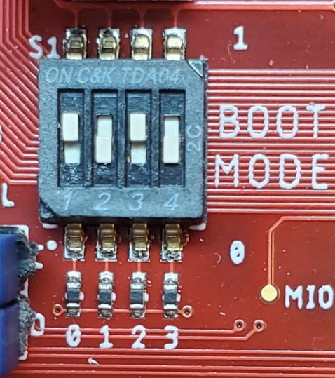
The OSDZU3-REF by default is set to boot from µSD card. It provides other boot options as well. These options are set using the 4-bit switches next to the USB host port.
To boot from µSD card, the boot switches must be set to SD1 as shown below. Please note that the Least Significant Bit (LSB) is on the left edge of the boot switch corresponding to “1” on-switch marking, and the Most Significant Bit (MSB) is on the right edge of the boot switch corresponding to “4” on-switch marking. The boot mode bits must be read from Right to Left (MSB to LSB) instead of the conventional left to right.
All the other boot mode options can be found in the OSDZU3-REF Schematics (see Note 2).
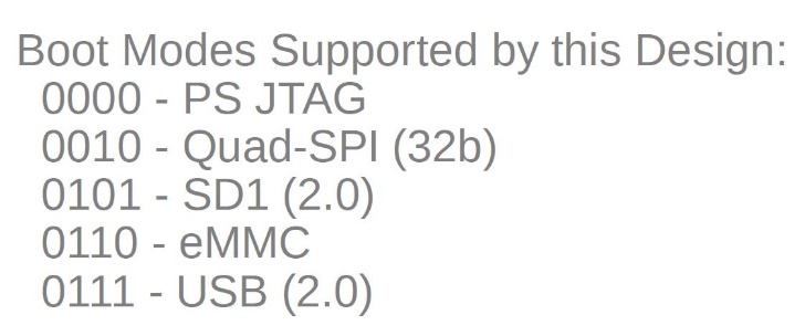
eMMC boot is not available on the versions of the OSDZU3-REF with the OSDZU3 Engineering Samples. This is because for ES devices, QSPI is connected to 3.3V power supply. Therefore, Bank 500 must be 3.3V IO. This means the eMMC interface (Bank 500) is using 3.3V IO. eMMC boot is available for 1.8V IO only. See section “Boot Modes” of Zynq Ultrascale+ TRM.
See ES Errata for more information on special considerations.
OSDZU3 Petalinux Software Image
The OSDZU3-REF comes with a µSD card pre-installed with Petalinux. This allows you to quickly evaluate different peripherals and interfaces as described in the following sections.
PetaLinux is a reference Linux distribution integrated and tested for AMD devices. The reference Linux distribution includes several packages including:
- Boot loader
- AMD CPU-optimized kernel
- Linux application libraries
- C, C++ and Python development tools
- Thread and FPU support
- Integrated web server
The Petalinux distribution from AMD has been adopted for OSDZU3 family and updated with following add-on packages, tools and PL IPs (PL instantiations) by our technology partner DesignLinx Hardware Solutions Inc for Octavo Systems:
- PL IP to support LVDS display output
- PL IP to provide I2C, UART, PWM and GPIO support for PMOD, Click and User IO interfaces
- C, C++ and Python development tools –
- gcc, g++, pip, pip3, smbus
- Nano editor
- Zip archive manager
You can download the latest version of the Petalinux SD Card Image here:
You can also find the source and project files on the Software Section of the OSDZU3-REF product page.
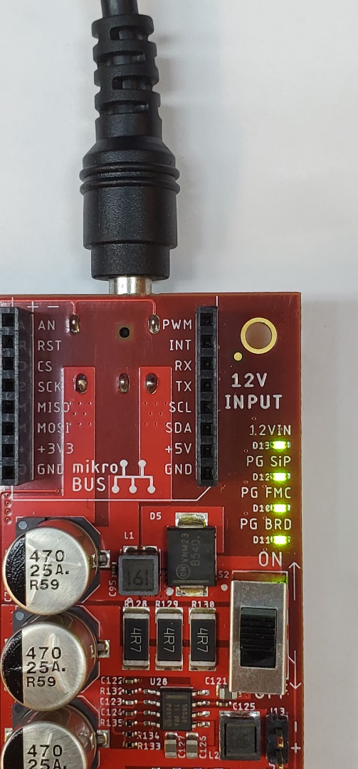
Powering the OSDZU3-REF
The OSDZU3-REF can be powered through the DC barrel connector with the provided power supply. The included power supply is capable of delivering at least 3A@12VDC with a center-positive barrel connector of 2.5mm inner diameter and 5.5mm outer diameter. If you would like to use your own power supply, it must meet this spec.
Once the board is connected to power, flip the power switch (S2) to ON position. The 12VIN LED (D13) should illuminate indicating input power. The other three Power Good (PG) LEDs i.e., PG SiP, PG FMC and PG BRD should also come up indicating successful power up of SiP, FMC and the Reference Board respectively. The power switch (S2) can be used to turn the board ON/OFF as necessary.
Interacting with the OSDZU3-REF
The OSDZU3-REF with the default image supports 3 ways to interact with it:
- UART
- JTAG (on-board and external)
- External display, keyboard & mouse
This section will go through each of these approaches. It is assumed that the OSDZU3-REF is connected to the power supply but switched off for each of these approaches.
UART
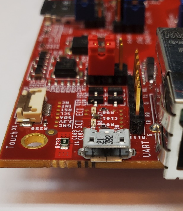
UART console provides critical, useful boot log information during OSDZU3 boot that helps debug any potential boot issues and determine if various hardware peripherals have come up successfully. Two UART interfaces (UART0 and UART1) of the OSDZU3 are made available on the OSDZU3-REF via µUSB port (thanks to USB to Dual UART Bridge) for added flexibility. By default, the Petalinux image provided by OctavoSystems uses UART1 interface for boot log output. We highly recommend that you access the UART console by connecting a USB-A to µUSB cable between the OSDZU3-REF and your PC. To do this:
- Make sure you have the necessary USB-UART bridge driver installed on your post PC. They can be downloaded from here.
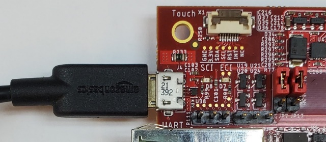
- Connect the OSDZU3-REF via the UART µUSB to a host computer.
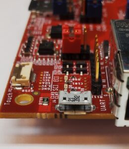

UART µUSB interface 

USB cable connected to UART µUSB port - Open Serial Console Client on your PC like Putty.
- You will see 2 UART ports appear on your host computer. For example, you may see something like COM6 and COM7 under Windows OS Device Manager’s COM ports or /dev/ttyUSB0 and /dev/ttyUSB1 under Linux based OS like Ubuntu. Choose the port with higher index for UART1 (COM7 or /dev/ttyUSB1 in this example)
Note: The actual COM port or TTY interface index you see on your computer may be different. - Set the baud rate of your Serial (UART) connection to 115200 on your client
(other parameters of the serial port can be left in their default state i.e., Data Bits = 8, Stop Bits = 1, Parity = None, Flow Control = XON/XOFF). - Set the Boot Mode to SD1 (i.e., BOOT MODE [3:0] = 0, 1, 0, 1).
- Insert the given µSD card in the slot (J1).
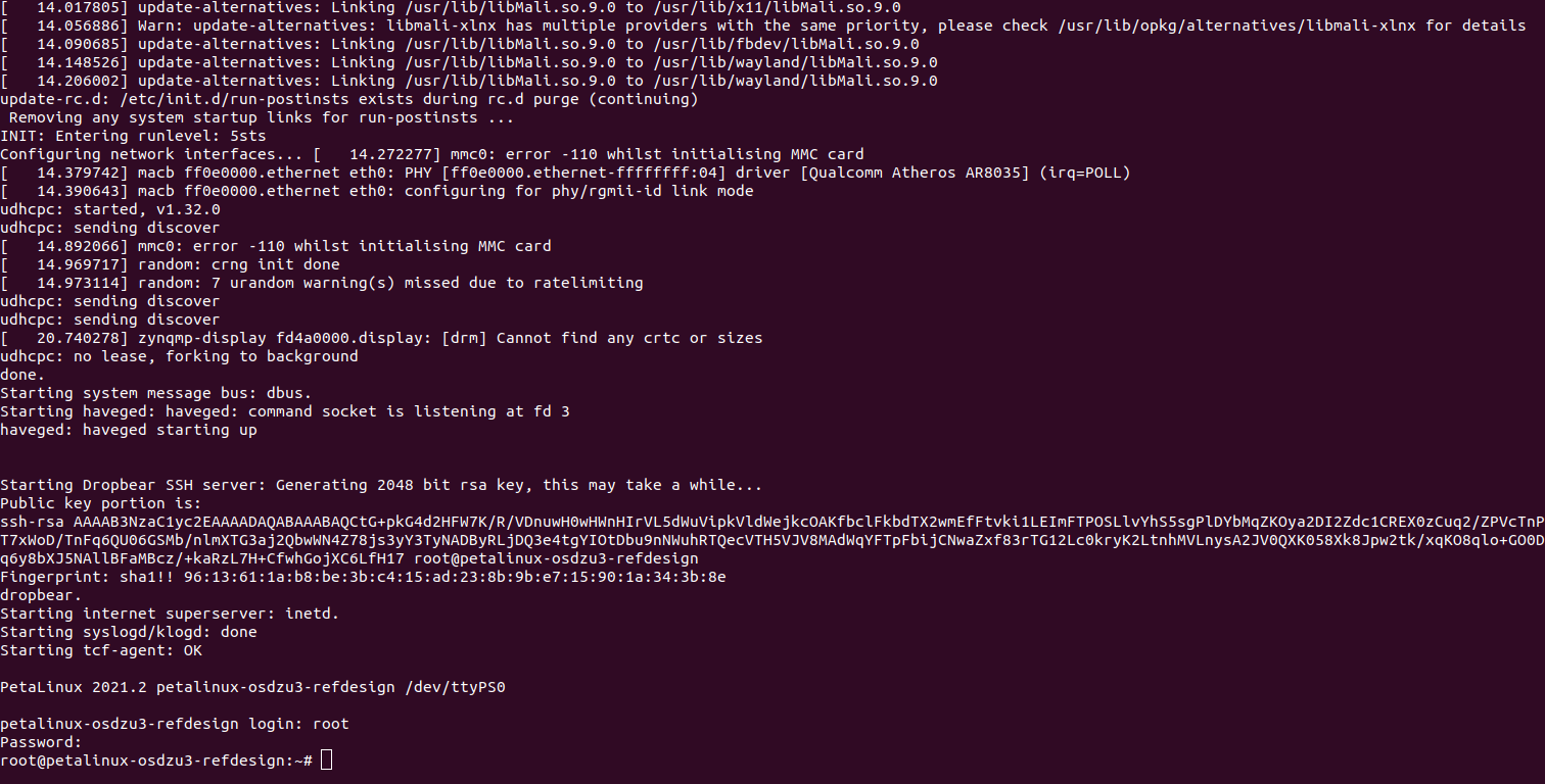
- Turn ON the platform by flipping the power switch (S2) and the boot messages should scroll by.
- If your µSD card has available empty space, you may a see a prompt from Disk Expander Script as shown below. The Disk Expander Script will help you maximize rootfs partition size to occupy all of the remaining empty space on the µSD card. If you wish to proceed with the rootfs expansion process, input “y” from the keyboard and press Enter. Otherwise, input “n” to skip this prompt until next reboot.
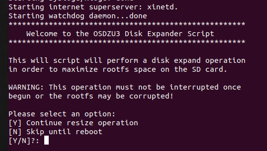

OSDZU3 Disk Expander Script Prompt - Once the boot is complete you will be prompted for the Linux Login. By default, the log in is:
- User Name: root
- Password: root
JTAG
OSDZU3-REF platform provides 2 ways to connect via JTAG:
- The On-board JTAG-SMT2™ Programming Module
- The J11 JTAG header which requires a AMD SmartLynq Data Cable to connect. This method is outside the scope of this app note, but you can refer OSDZU3 Vivado Tutorial for more information.
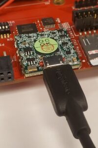
The On-board JTAG-SMT2™ Programming Module is a fully self-contained USB to JTAG module from Digilent that can be directly accessed from Vivado or Vitis. The steps to establish a successful JTAG connection over Vivado and Vitis are described below.
- Connect a µUSB to USB-A cable between the JTAG-SMT2™ Programming Module and your host computer running Vivado/Vitis.

Digilent JTAG to USB Module - Set the Boot Mode to PS JTAG (i.e., BOOT MODE [3:0] = 0, 0, 0, 0).
- Turn ON the platform by flipping the power switch (S2).

On Vivado:
- Open Vivado on your host computer
- In Vivado toolbar, go to Flow > Hardware Manager
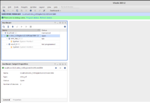
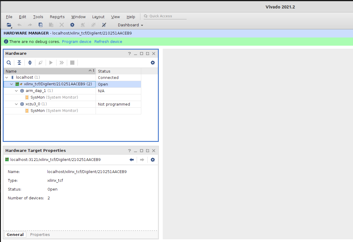
- Once Hardware Manager opens, click on Tools > Auto Connect
- The digilent module will show up under localhost as shown below.

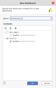
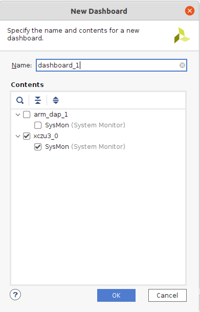
Vivado Hardware Manager - Double click on SysMon under xczu3_0. A new Dashboard window will open. Put in a name for the dashboard and click OK.

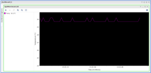
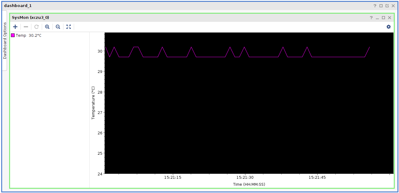
Vivado New Dashboard window - Sysmon dashboard will appear indicating ZU3 SoC temperature.

Sysmon Dashboard
On Vitis:
- Open Vitis on your host computer
- In Vitis toolbar, go to > Window > Show View > Xilinx > Target Connections
- Under Hardware Server:
- See if a default Local target is visible as shown below.
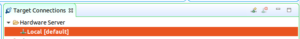

Default Local target - If yes, right click on Local and press View. Target connection details should be similar to what is shown below.
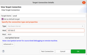

Target Connection Details - Click on Test Connection and verify if the connection is successful.
- See if a default Local target is visible as shown below.
- If no default targets are available under Hardware Server, create a new target:
- Right click on Hardware Server > New Target
- Set Target Name to OSDZU3-Ref-JTAG, other parameters as follows and click OK:
- Type: Hardware Server
- Host: 127.0.0.1
- Port: 3121
- Use Symbol Server Checkbox: Check it
- Click on Test Connection and verify if the connection is successful.
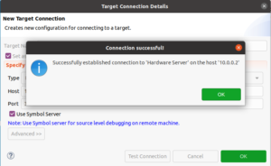

JTAG successfully connected
- Newly added OSDZU3-Ref-JTAG [default] hardware server should appear under Target Connections window.


- For Linux Host PC: https://digilent.com/reference/programmable-logic/guides/install-cable-drivers
- For Windows 10 Host PC: https://support.xilinx.com/s/article/1013230?language=en_US
External display, keyboard & mouse
To interact seamlessly with the Graphical User Interface (GUI) of the OSDZU3-REF, you can:
- Connect an external display via:
- Display Port interface or
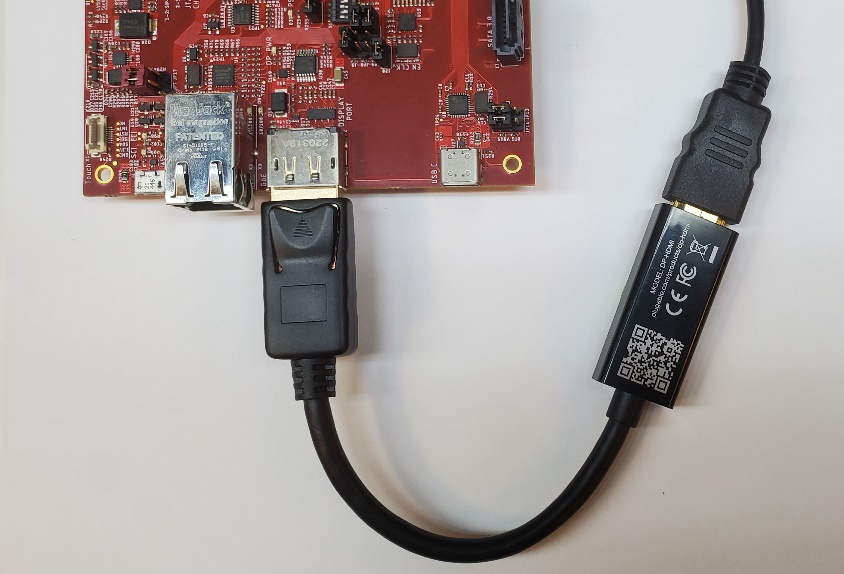
- Use the provided Display Port to HDMI adapter.
Refer Display Port output section below for more info.
- Connect a USB-C keyboard and mouse. Refer USB-C Host section below for more info.
- Insert the provided µSD card in the slot J1.
- Set the Boot Mode to SD1.
- Turn ON the platform by flipping the power switch (S2).
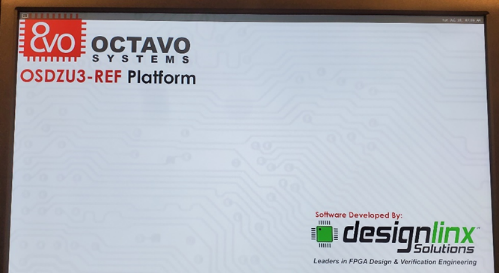
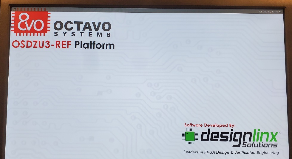
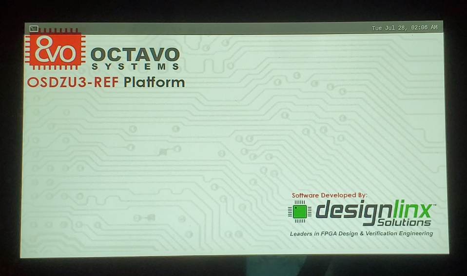
OSDZU3-REF external display desktop is shown in image below.
OSDZU3-REF Platform Peripherals
The OSDZU3-REF has many common peripherals that are used in a wide variety of applications. This section will briefly explain how to use them with their default functionality.
Display Port output
By default, the Petalinux Image provided my Octavo Systems uses Display Port (DP) for external display output. Simply plug in a display port cable into the OSDZU3-REF and the other end into a Display Port monitor and you will see the default desktop. The Display Port can support up to 4K x 2K video @30 Hz video resolution as highlighted here https://docs.xilinx.com/r/en-US/ug1449-multimedia/DisplayPort-Interface.
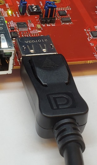
If you do not have access to a display that supports Display Port you can use the provided DP to HDMI adaptor to connect to an HDMI monitor. You will then be able to see the default desktop. The maximum supported HDMI output resolution is same as Display Port maximum mentioned above.
LVDS Touch Display
OSDZU3, by default, provides Display Port interface for video output. Display Port is excellent for computer monitors and other larger displays. However, for handheld and other smart devices that require smaller screens, Display Port interface is seldom used. To bridge this gap, our technology partner DesignLinx Hardware Solutions Inc. has developed a dedicated LVDS Display PL IP for Octavo Systems. This IP powers the LVDS display connector on OSDZU3-REF board.
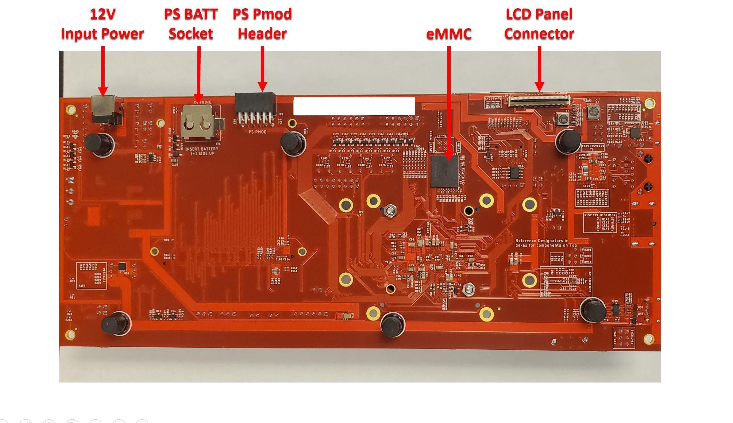
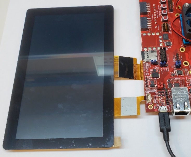
OSDZU3-REF has one LVDS display panel connector (40pin, 0.5mm pitch, right-angle) on the bottom edge of the board, one touch connector (8pin, 0.5mm pitch, right-angle) on the top edge as shown in below picture below. OSDZU3-REF can support LVDS displays up to 3840 x 2160 resolution.
The default Octavo Systems Petalinux image will automatically switch between Display Port and LVDS. The Display Port is the priority display and will be selected as the output whenever it is connected. In order for the display to be output on the LVDS, the Display Port must not be connected.
LVDS displays that are known to work well with the Octavo Systems LVDS IP (at the time of writing this app note) are listed below. Please note that the device tree for the OSDZU3-REF must be changed to reflect the actual LVDS display panel and touch module being connected. The default device tree setting is for the GLT0701024600IS2-CTP panel shown below.
- GLT0701024600IS2-CTP (https://www.digikey.com/en/products/detail/global-technologies-group-inc/GLT0701024600IS2-CTP/13997788)
- DT070DTFT-IPS-HB (https://www.digikey.com/en/products/detail/displaytech/DT070DTFT-IPS-HB/11561140)
Backlight brightness control
To power the LCD backlights, a dedicated LCD backlight driver IC is available on-board. LCD backlight can be configured using jumpers JP7 and JP17. Set the jumpers in their default positions shown below.
| Position 1-2 | Always enabled (default) |
| Position 2-3 | Control by ZU3 |
| Position 1-2 | Control by ZU3 (default) |
| Position 2-3 | Disabled |
The LVDS display backlight brightness can be controlled by writing brightness level (0 to 7) to brightness in /sys/class/backlight/backlight under Petalinux. Lowest brightness level is 0 and the highest is 7.
root@peta1inux—osdzu3—refdesign:/sys/class/backlight/backlight# echo 0 > brightness
root@peta1inux—osdzu3—refdesign:/sys/class/backlight/backlight# echo 3 > brightness
root@peta1inux—osdzu3—refdesign:/sys/class/backlight/backlight# echo 7 > brightness
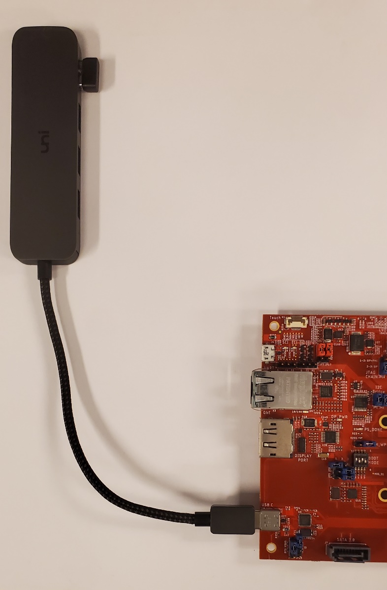
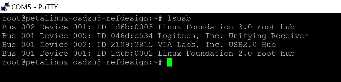
USB-C Host
The OSDZU3-REF has a USB3.0 Super Speed USB-C Host Interface that can be used to interface to a wide range of USB devices. An USB-C to USB-A hub may be required to connect devices with USB-A port.
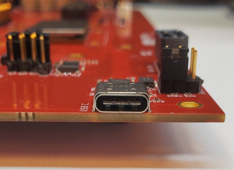
Here is an example of a Logitech keyboard + mouse USB dongle connected to the USB-C host port via a USB-C Hub.
Ethernet
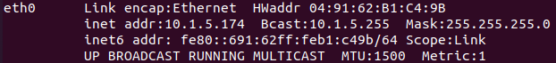
The OSDZU3-REF has a 1Gbit Ethernet port. This can be used to connect to any network and provide internet access. To use the Ethernet port, connect an ethernet cable to the OSDZU3-REF and to a compatible network switch.
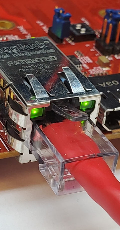
If your network automatically assigns IP Addresses via DHCP the OSDZU3-REF will automatically receive an IP address.
eMMC
OSDZU3-REF comes with a blank on-board eMMC. eMMC boot is not currently supported on the OSDZU3-REF as outlined in Note 2 under Boot Options section.
You can start using eMMC as nonvolatile on-board storage once you mount it and reformat it as follows:
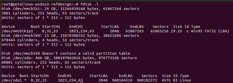
- List all the available memory blocks using fdisk -l command. eMMC is /dev/mmcblk0.
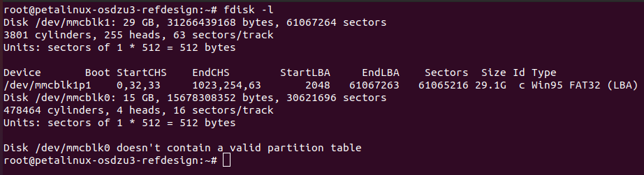

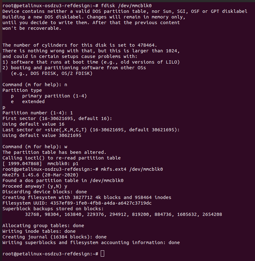
Example fdisk-l command with the eMMC - Create a new partition using following steps:
- fdisk /dev/mmcblk0
- Type n to create a new partition
- Type p to choose primary partition
- Type 1 for partition number, use default first and last sectors by hitting enter
- Type w and hit enter to write the changes to eMMC
- Format the newly created partition using command: mkfs.ext4 /dev/mmcblk0
- Create mount point: mkdir /emmc (can be any folder you want)
- Mount the disk: mount /dev/mmcblk0 /emmc
You can now use /emmc mount point to write and read data from the emmc.
SATA
The OSDZU3-REF comes with a SATA (Rev3.1) port. When you plug in a SATA drive you may see UART console messages indicating the SATA link coming up, its speed and other hardware information.
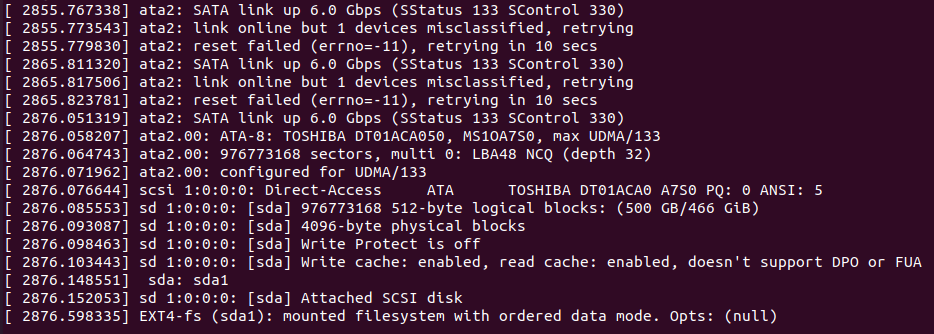
You can check for SATA drive using fdisk -l command. SATA drive is /dev/sda (466GB) in our example shown below. SATA drive can be partitioned, mounted and used as a mass storage device using the steps already laid out in the eMMC section above.
EEPROM
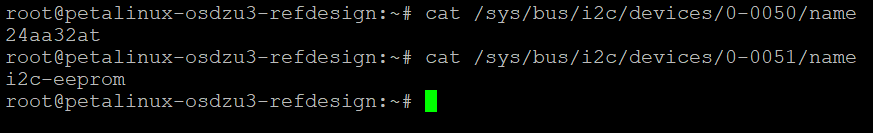
OSDZU3-REF has two EEPROMs available:
- 32Kb EEPROM internal to the OSDZU3 SiP with I2C address: Bus 0, 0x50
- 2Kb on-board EEPROM with I2C address: Bus 0, 0x51
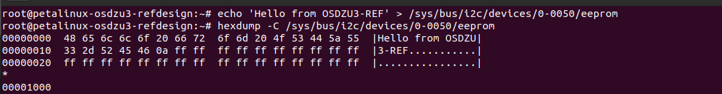
As a simple demo, we can write to and read from the OSDZU3 SiP’s internal EEPROM using “echo” and “hexdump” commands respectively, as shown in the below figure.
Ensure EPRM_WP on-board jumper is populated to disable the internal EEPROM’s write protection before writing to the EEPROM. When populated, EPRM_WP jumper shorts EEPROM_WP pin of the OSDZU3 SiP to GND. More info on this is available in the OSDZU3 datasheet and OSDZU3-REF schematic.
OSDZU3-REF Platform Expansion
The OSDZU3-REF also has standard expansion interfaces that can be used to add functionality to the OSDZU3-REF platform. This section will provide a high-level overview of each of the expansion options.
Pmod
The Pmod interface is used to connect low frequency, low I/O pin count peripheral modules (i.e., SPI, I²C, UART, I2S, H-bridge or GPIO protocols) to the OSDZU3-REF. The board provides dual PL Pmod ports (2 x 12 pins) and one PS Pmod port (1 x 12pins).
Various Pmod add-on boards are available here:
https://digilent.com/shop/boards-and-components/system-board-expansion-modules/pmods/
PMOD specification is available here:
https://digilent.com/reference/_media/reference/pmod/pmod-interface-specification-1_2_0.pdf
PS PMOD header
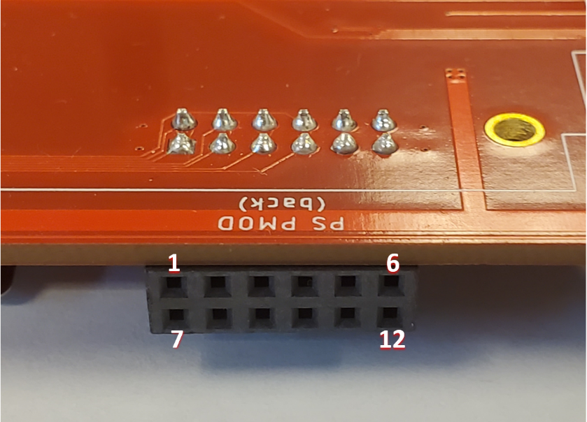
The pinout of PS PMOD header is given below.
| PMOD pin # | OSDZU3 pin | Function | Petalinux Kernel Default Object | Comments |
|---|---|---|---|---|
| 1 | MIO_41 | CS | spi0 n_ss_out[0] | |
| 2 | MIO_43 | MOSI | spi0 mosi | Shared with Click Interface, populate J22 to use MIO_36, populate J21 to use MIO_37 |
| 3 | MIO_42 | MISO | spi0 miso | |
| 4 | MIO_38 | SCK | spi0 sclk_out | |
| 5 | GND | GND | – | |
| 6 | +3.3V | +3.3V | – | |
| 7 | MIO_36 | INT | gpiochip9 36 | |
| 8 | MIO_37 | RESET | gpiochip9 37 | |
| 9 | MIO_39 | CS2 | spi0 n_ss_out[2] | |
| 10 | MIO_40 | CS1 | spi0 n_ss_out[1] | |
| 11 | GND | GND | – | |
| 12 | +3.3V | +3.3V | – |
PL PMOD headers
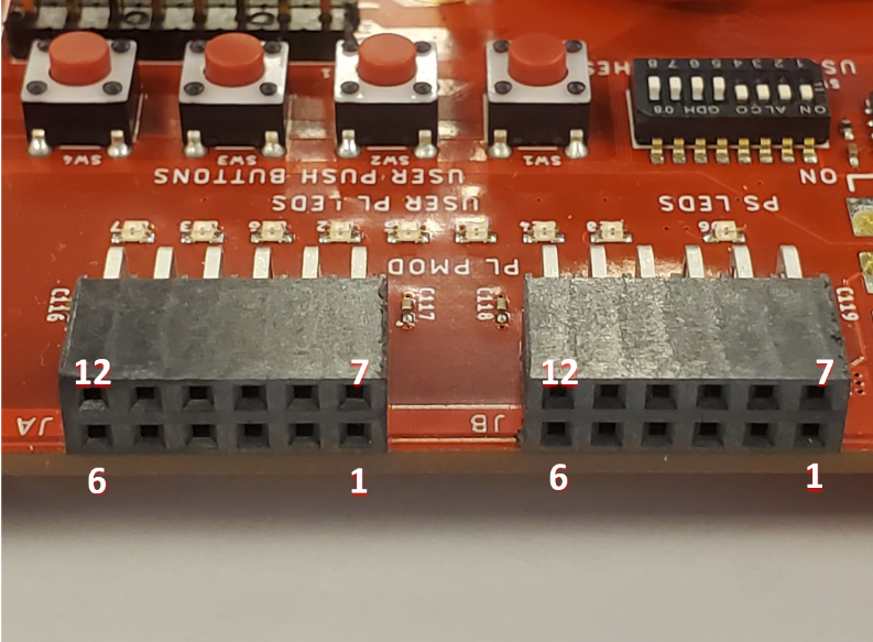
The pinout of PL PMOD headers is given below.
| PMOD pin # | OSDZU3 pin | Function | Petalinux Kernel Default Object | Comments |
|---|---|---|---|---|
| 1 | JX2_HD_SE_03_P | CTS | ttyS2 (baud rate: 9600) | UART & GPIO interfaces are instantiated in PL by DesignLinx Hardware Solutions Inc. for Octavo Systems. |
| 2 | JX2_HD_SE_05_GC_P | TXD | ||
| 3 | JX2_HD_SE_07_GC_P | RXD | ||
| 4 | JX2_HD_SE_09_P | RTS | ||
| 5 | GND | GND | – | |
| 6 | +3.3V | +3.3V | – | |
| 7 | JX2_HD_SE_03_N | INT | gpiochip4 0 | |
| 8 | JX2_HD_SE_05_GC_N | RESET | gpiochip4 1 | |
| 9 | JX2_HD_SE_07_GC_N | GPIO | gpiochip4 2 | |
| 10 | JX2_HD_SE_09_N | GPIO | gpiochip4 3 | |
| 11 | GND | GND | – | |
| 12 | +3.3V | +3.3V | – |
| PMOD pin # | OSDZU3 pin | Function | Petalinux Kernel Default Object | Comments |
|---|---|---|---|---|
| 1 | JX2_HD_SE_02_P | INT | gpiochip5 0 | I2C & GPIO interfaces are instantiated in PL by DesignLinx Hardware Solutions Inc. for Octavo Systems. |
| 2 | JX2_HD_SE_04_GC_P | RESET | gpiochip5 1 | |
| 3 | JX2_HD_SE_06_GC_P | SCL | i2c bus 3 | |
| 4 | JX2_HD_SE_08_P | SDA | ||
| 5 | GND | GND | – | |
| 6 | +3.3V | +3.3V | – | |
| 7 | JX2_HD_SE_02_N | GPIO | gpiochip5 2 | |
| 8 | JX2_HD_SE_04_GC_N | GPIO | gpiochip5 3 | |
| 9 | JX2_HD_SE_06_GC_N | GPIO | gpiochip5 4 | |
| 10 | JX2_HD_SE_08_N | GPIO | gpiochip5 5 | |
| 11 | GND | GND | – | |
| 12 | +3.3V | +3.3V | – |
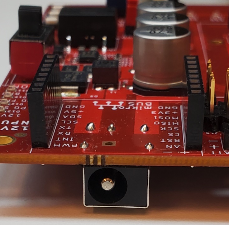
mikroBUS (for Click boards)
The OSDZU3-REF features a mikroBus header to help users take advantage of a wide range of sensors, actuators and UI devices available via pluggable Mikro Click add-on boards.
mikroBUS provides three groups of communications pins (SPI, UART and I2C), five additional pins (PWM, Interrupt, Analog input, Reset and Chip select), and two power groups (+3.3V, GND & 5V, GND).
See table below for detailed information on the available Click interfaces.
mikroBUS specification is available here: https://download.mikroe.com/documents/standards/mikrobus/mikrobus-standard-specification-v200.pdf
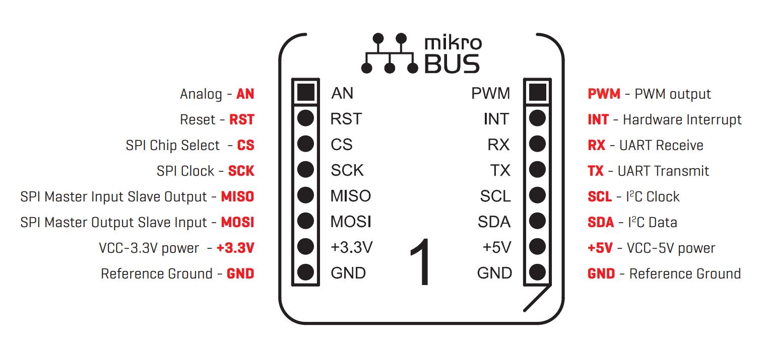
OSDZU3 pin to click header pin mapping is given in table below.
| Click header pin | OSDZU3 pin | Petalinux Kernel Default Object | Comments |
|---|---|---|---|
| AN | ADC (PS) | i2c 2-0014 | Uses dedicated I2C ADC on I2C1 bus, address 0x52 |
| RST | MIO_37 (PS) | gpiochip9 37 | Shared with PS_PMOD Interface, populate jumper J15 to use |
| CS | MIO_41 / MIO40 (PS) | spi0 n_ss_out[0] or spi0 n_ss_out[1] | Shared with PS_PMOD Interface; use jumper JP6 to choose between MIO_40 and MIO_41 |
| SCK | MIO_38 (PS) | spi0 sclk_out | Shared with PS_PMOD Interface |
| MISO | MIO_42 (PS) | spi0 miso | Shared with PS_PMOD Interface |
| MOSI | MIO_43 (PS) | spi0 mosi | Shared with PS_PMOD Interface |
| INT | MIO_36 (PS) | gpiochip9 36 | Shared with PS_PMOD Interface, populate jumper J16 to use |
| PWM | 44N_L6 (PL) | pwmchip0 | UART, I2C & PWM interfaces are instantiated in PL DesignLinx Hardware Solutions Inc. for Octavo Systems. |
| RX | 44N_L5 (PL) | ttyS3 (baud rate: 9600) | |
| TX | 44P_L5 (PL) | ||
| SCL | 44N_L7 (PL) | i2c bus 1 | |
| SDA | 44P_L7 (PL) |
FPGA Mezzanine Card (FMC) Low Pin Count (LPC) interface
The FPGA Mezzanine Card (FMC) is an ANSI standard that provides a standard mezzanine card form factor, connectors, and modular interface to an FPGA located on a base board. Decoupling the I/O interfaces from the FPGA simplifies I/O interface module design while maximizing carrier card reuse. FMC was developed by a consortium of companies ranging from FPGA vendors to end users.
The FMC LPC interface on the OSDZU3-REF provides:
- 34 user-defined, differential pairs
- 2 user differential clock pairs
More detailed information on FMC cards is available here – https://fmchub.github.io/appendix/VITA57_FMC_HPC_LPC_SIGNALS_AND_PINOUT.html
FMC LPC interface usage requires suitable PL instantiation and OSDZU3-REF does not support FMC LPC interface usage out-of-the-box. Further discussion on FMC LPC is beyond the scope of this document.
FMC cards for various applications are available here – https://www.xilinx.com/products/boards-and-kits/fmc-cards.html
OSDZU3 Additional Interfaces
The OSDZU3-REF also has several on-board user LEDs, buttons and switches connected to both the PS and the PL of the OSDZU3 for easy interaction with the board.
The PL IP required to enable User GPIO functionality is developed by our technology partner DesignLinx Hardware Solutions Inc. for Octavo Systems.
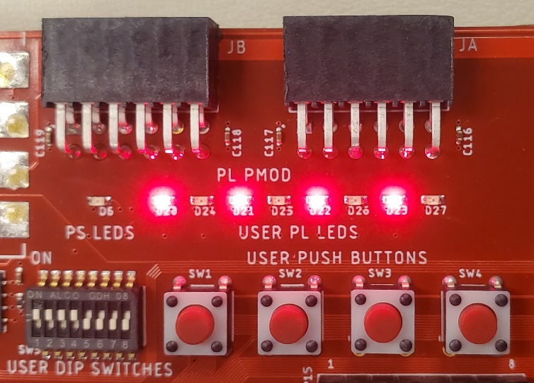
LEDs
The 8 PL User LEDs and one PS User LED are available under sysfs (/sys/class/leds) . The LED names are based on their respective on-board designators (D20, D24, D21 etc) and are listed below.
- PL User LEDS
- led0-d20/
- led1-d24/
- led2-d21/
- led3-d25/
- led4-d22/
- led5-d26/
- led6-d23/
- led7-d27/
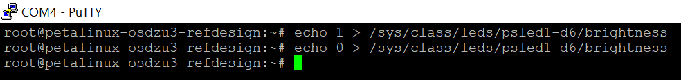
- PS User LED
- psled1-d6/
The LEDs can be turned ON or OFF by writing 1 or 0 to their “brightness” property.
echo 1 > /sys/class/leds/led0-d20/brightness
echo 0 > /sys/class/leds/led0-d20/brightness
As a simple demo, you can use the following command to make a pattern shown below.

User DIP Switches
The PL standard GPIOs can be accessed using the libgpiod utilities that come with Petalinux. You can view all the available GPIOs by running the “gpiodetect” command.
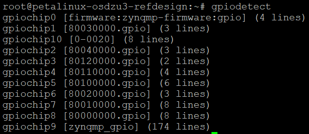
The 8 PL User DIP Switches are available in petalinux under “gpiochip8”. The switch number and the corresponding GPIOchip8 number is outlined in the table below.
| User PL DIP Switch Number on SW5 | Gpiochip8 number |
|---|---|
| 1 | 0 |
| 2 | 1 |
| 3 | 2 |
| 4 | 3 |
| 5 | 4 |
| 6 | 5 |
| 7 | 6 |
| 8 | 7 |
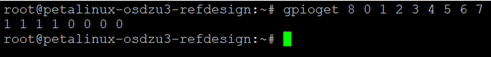
You can check their input status using the following command.
gpioget 8 0 1 2 3 4 5 6 7
User Push Buttons
The 3 PL User Push Buttons SW1, SW2, SW3 are available in petalinux under “gpiochip6”. SW4 is configured as a PL reset button in the default reference board configuration. It can be reconfigured for other purposes in the hardware platform for the OSDZU3-REF.
| User PL Push Button on-board designator | Gpiochip6 Pin Number |
|---|---|
| SW1 | 0 |
| SW2 | 1 |
| SW3 | 2 |
| SW4 | PL Reset |
To access the state of the push buttons, use the gpioget command with the gpiochip number followed by the gpio pin numbers.
gpioget 6 0 1 2
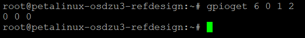
Example Output of Button State
Revision History
| Revision Number | Revision Date | Changes | Author |
| 1 | 01/03/2023 | Initial Revision | Eshtaartha Basu |
| 2 | 02/17/2023 | Minor updates - Revision History table added, Additional Interfaces section updated | Greg Sheridan |
| 3 | 07/19/2023 | Minor updates to sections Platform Overview, Boot Options, Powering the OSDZU3-REF, UART, JTAG, EEPROM, Additional Interfaces. Tutorial Requirements section added. | Eshtaartha Basu |
