OSD32MP1 Power Budgeting
Published On: September, 9, 2020 By: Neeraj Dantu
It is good practice to create a power budget for a design/product when starting the design. Good power budgeting contributes to circuit robustness, increased product life, and reduced cost of the product. To create a power budget, information on power consumption of the components, power availability, operating temperature, communication, and operation modes of the processor needs be collected.
This App Note will outline the different aspects that should be considered when creating a power budget for an OSD32MP1 based design.
As part of the power budget you may want to leverage different power modes of the STM32MP1. Please refer to the Low Power App Note for the OSD32MP1 for more information on using the low power modes.
If you need more information on how the power system of the OSD32MP1 fucntions please see this app note.
Table of Contents
Step 1: Creating a Power Diagram
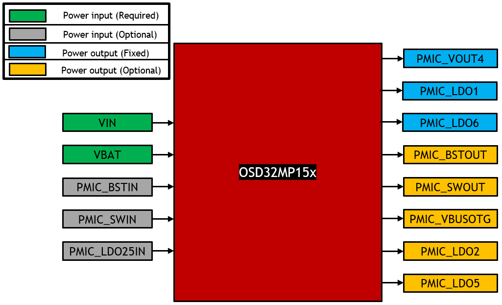
To create a power budget, the first step is creating a power diagram that shows all the power paths of the system. For the OSD32MP15x, this includes both input and output power rails shown in the following figure. Each output should be labelled with the voltage that will be used in the system and the maximum current supported from the datasheet.
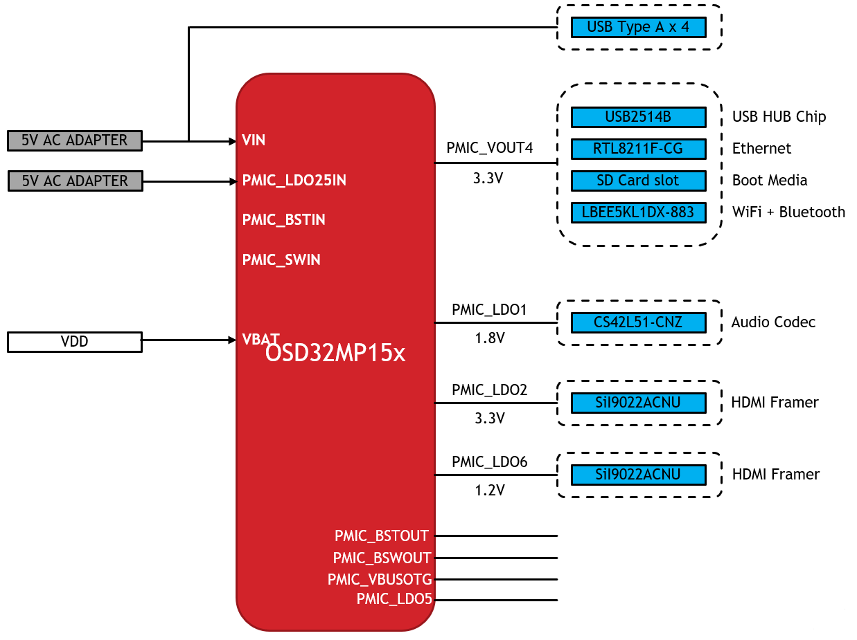
Next, based on the input voltage required, each power consuming components should be added and connected to the appropriate output power rail. Once all of the components have been placed on the appropriate outputs, the SiP power inputs can be connected to the appropriate input power supply, or left unconnected if not used. The figure below shows the completed power system diagram for the OSD32MP1-DK2 Platform. The schematics and design files for this board are available here.
Step 2: Creating a Power Budget
Once a power block diagram has been created, the next step is making a power budget to estimate power consumption of each component and thus the total power consumption of the design.
Maximum Power
There are several challenges involved in accurately estimating the power consumption of each component. For example, it is difficult to estimate how much current, the STM32MP15x processor and the DDR Memory draw since that is highly application dependent. Power consumption can also depend on the presence of an externally connected device, such as a USB device or a microSD card. To account for all situations, start by listing the maximum power consumption for all the components. Maximum current consumption values can be found in each component datasheet. The table below shows the power budget for the OSD32MP1-DK2 assuming maximum power consumption for each component.
| PART NAME | PART # | CURRENT (mA) | VOLTAGE RAIL | EFF* (%) | RAIL VOLTAGE (V) | LDO PARENT | POWER(mW) |
|---|---|---|---|---|---|---|---|
| STM32MP15x | U13 | 440 | Internal | 100 | 1.2 | – | 528 |
| STPMIC1A | U13 | 1.2 | Internal | 100 | 5 | – | 6 |
| DDR3L | U13 | 360 | Internal | 84 | 1.35 | – | 579 |
| 4KB EEPROM | U13 | 3 | Internal | 79 | 3.3 | – | 13 |
| USB Conn | CN1/CN5 | ~250 | VIN | 100 | 5 | – | ~1250 |
| SII9022 | U14 | 9.6 | PMIC_LDO2 | – | 3.3 | 5 | 48 |
| SII9022 | U14 | 69.2 | PMIC_LDO6 | – | 1.2 | 3.3 | 228 |
| LBEE5KL1DX | U8 | 370 | PMIC_VOUT4 | 79 | 3.3 | – | 1546 |
| SD CARD | CN15 | 200 | PMIC_VOUT4 | 79 | 3.3 | – | 835 |
| RTL8211F-CG | U18 | 180 | PMIC_VOUT4 | 79 | 3.3 | – | 752 |
| USB2514B | U7 | 80 | PMIC_VOUT4 | 79 | 3.3 | – | 334 |
| CS42L51-CNZ | U20 | 11.18 | PMIC_LDO1 | – | 1.8 | 3.3 | 37 |
| TOTAL | 6156 |
*Note that this is the worst-case efficiency of the power rail. It is used to calculate for worst-case scenario for a robust power design.
This shows a total, worst-case power consumption. While this is useful to keep in mind when thinking about your power layout and thermal design, normal operation of the device will not consume that much power. Therefore, the power budget should be refined to better reflect normal operation.
Typically, application specific power consumption values for each of the devices can also be gathered from the datasheet. However, calculating the power consumption for the SoC is a little more involved. The following section demonstrates the procedure to use the STM32CubeMX tool for estimating the power consumption for the SoC.
Estimating STM32MP1 Power Consumption
STM32CubeMX provides a power estimation tool that can calculate power consumption of the STM32MP15x in different power modes, including low power modes. Set up for STM32CubeMX is described in the STM32MP1 CubeMX Tutorial for OSD32MP15x application note. To use the power tool:
- Review STM32MP1 CubeMX Tutorial and download the necessary components.
- Open the Minimal CubeMX Project for the OSD32MP15x.
- Modify the peripheral and pinout configuration according to the connections required for the application.
- Navigate to the tools section and click on the PCC tab.
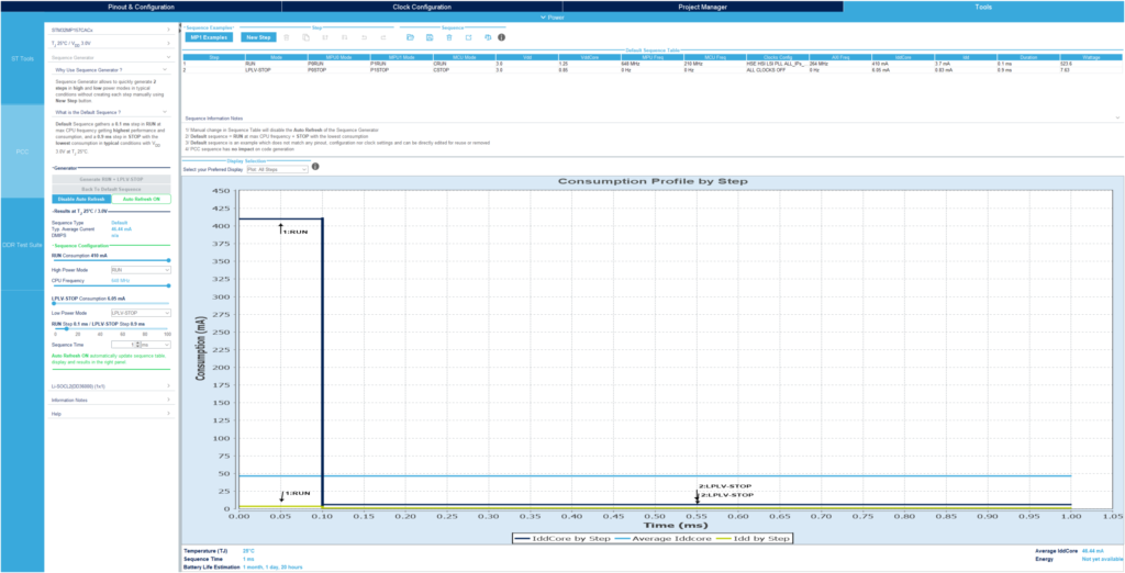

Tools Tab - The junction temperature of the SoC for the target application can be calculated using OSD32MP15x Thermal Guide. There are only two options for the junction temperature in CubeMX: room temperature and worst case. Set the junction temperature and VDD. The worst-case junction temperature(85C) was used for this example.
- The tool estimates power based on the state of each core of the SoC and the clock configuration of the peripherals. Each configuration lasts for a set time period called a “step”. By default, the tool generates two steps: RUN and LPLV-Stop. Click on “Generate RUN + LPLV-STOP” button.
- You can modify the default steps to change MPU and MCU power modes and frequencies by double clicking the step in the sequence table. In this window, you can also choose different frequencies or change peripheral allocation.
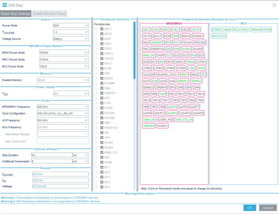

Step Settings - You can also add your own steps by clicking the new step button.
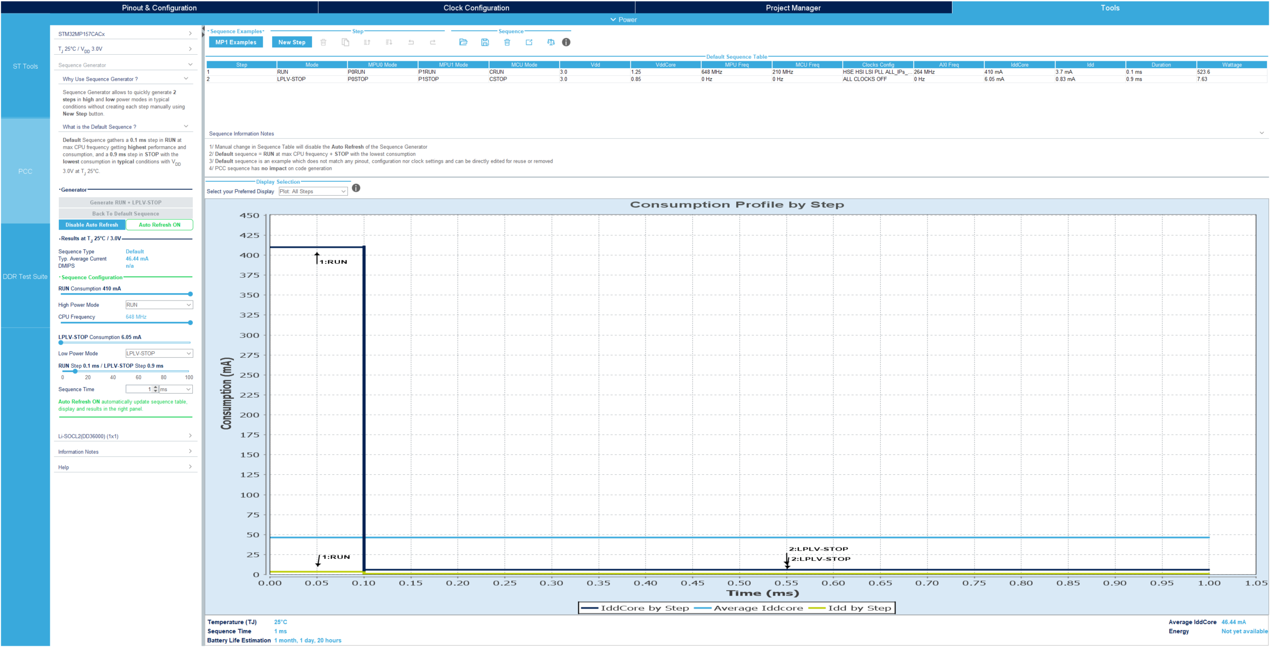
The Step configuration window gives a good estimate of the power consumption value we need to refine the power estimation of the SoC. The following information was gathered from the tool:
| VOLTAGE RAIL | CURRENT CONSUMPTION (mA) |
|---|---|
| VDD_CORE | 470 |
| VDD | 4 |
You can see more details about the power estimation tool in Section 5.1 of the STM32CubeMx for STM32 configuration and initialization C code generation – User Guide from the ST website.
Based on the above consumption numbers, the total power consumption for the SoC can be calculated as follows:
| POWER RAIL | CURRENT COSUMPTION (mA) | VOLTAGE (V) | PMIC POWER RAIL | EFFICIENCY (%) | POWER CONSUMPTION (mW) |
|---|---|---|---|---|---|
| VDD_CORE | 470 | 1.2 | VOUT1 | 70 | 806 |
| VDD | 4 | 3.3 | VOUT3 | 88 | 15 |
| TOTAL | 831 |
This is a much more reasonable number to use for power budgeting than the initial worst-case estimate of 2200mW.
Refining the Power Budget
Now that application specific SoC power consumption numbers have been calculated, the power budget can be update to more accurately reflect the actual application power consumption. Although it is safe to use the worst-case scenario power consumption values, the power system of the product/design will be severely over-designed.
Therefore, in the table below, more typical and application specific power consumption values have been used for the power budget. These typical power consumption values were taken from the datasheets of the respective devices. Note that the total power consumption still assumes usage of all the peripherals at once along with full usage of the SoC, but using this power budget to design the power system will make for a robust power design, accounting for any unexpected power usage.
| PART NAME | PART # | CURRENT (mA) | VOLTAGE RAIL | EFFICIENCY* (%) | VOLTAGE (V) | LDO PARENT | POWER (mW) |
|---|---|---|---|---|---|---|---|
| STM32MP15x | U13 | 166.2 | Internal | 100+ | 5 | – | 831 |
| STPMIC1A | U13 | 1.2 | Internal | 100** | 5 | – | 6 |
| DDR3L | U13 | 360 | Internal | 84 | 1.35 | – | 579 |
| 4KB EEPROM | U13 | 1 | Internal | 79 | 3.3 | – | 4 |
| USB Conn | CN1/CN5 | ~250 | VIN | 100 | 5 | – | ~1250 |
| SII9022 | U14 | 7 | PMIC_LDO2 | – | 3.3 | 5 | 35 |
| SII9022 | U14 | 54.2 | PMIC_LDO6 | – | 1.2 | 3.3 | 179 |
| LBEE5KL1DX | U8 | 270 | PMIC_VOUT4 | 79 | 3.3 | – | 1128 |
| SD CARD | CN15 | 80 | PMIC_VOUT4 | 79 | 3.3 | – | 334 |
| RTL8211F-CG | U18 | 110 | PMIC_VOUT4 | 79 | 3.3 | – | 459 |
| USB2514B | U7 | 35 | PMIC_VOUT4 | 79 | 3.3 | – | 146 |
| CS42L51-CNZ | U20 | 11.18 | PMIC_LDO1 | – | 1.8 | 3.3 | 37 |
| TOTAL | 4998 |
*Note that this is the worst-case efficiency of the power rail. It is used to calculate for worst-case scenario for a robust power design.
+Efficiency of power rail is already accounted for in the Power Consumption table
**Efficiency of power rail is already accounted for in the Power Consumption table
As mentioned, this power budget is still higher than what the actual application will use as all devices and peripherals are unlikely to be used at the same time. This can be thought of as a worst-case application scenario that can occur. However, designing for such a scenario makes for a robust power design.
Step 3: Calculate Total Input / Output Currents
From the application specific power budget, it is time to add up all of the currents to make sure that the current consumption on each power rail does not exceed the maximum current capacity of the power rail as specified in the datasheet.
| Condition | Limitation | Worst Case | Application Specific |
|---|---|---|---|
| VIN input current | 2.0 A | 1566 mA | 1000 mA |
| VIN_BAT input current | 2.0 mA | — | — |
| SWIN input current | 250 mA | — | — |
| PMIC_VOUT4 output current | 2.0 A | 833 mA | 496 mA |
| PMIC_LDO1 output current | 350 mA | 11.8 mA | 11.8 mA |
| PMIC_LDO2 output current | 350 mA | 9.6 mA | 7 mA |
| PMIC_LDO5 output current | 350 mA | — | — |
| PMIC_LDO6 output current | 150 mA | 69.2 mA | 54.2 mA |
| PMIC_BSTOUT output current | 500 mA | — | — |
| PMIC_VBUSOTG output current | 500 mA | — | — |
| PMIC_SWOUT output current | 250 mA | — | — |
While this design presents no problems for the power design (i.e. all currents are well under the specified limits), there might be situations where the current draws are close to or exceed the power rail limits in a design. In this case, the power architecture will need to be modified. The OSD32MP15x has multiple programmable power rails so components can be moved to different power outputs or other regulators can be added to the design.
System Power Estimation for Battery Applications
While the previous power budgets and current analysis must be done to create a robust power system, it only provides information about the Run state. This does not provide a complete picture when trying to understand battery life for battery powered applications. Given that applications will also use low power states to minimize power consumption when not in use, it is also good to estimate the average system power over time.
The best way to characterize the system power consumption over time is to estimate average power consumption per hour. This provides a straightforward way for battery powered applications to determine the necessary battery capacity for the use case. For example, assume an application scenario with the following characteristics:
| SYSTEM POWER STATE | PERCENTAGE OF TIME SPENT IN THIS STATE |
|---|---|
| Run | 20% |
| LP-Stop | 80% |
The LP-Stop power state allows for a quick wakeup from UART console and reduces the total power consumption of the application by a significant amount. This low power mode and the software mechanism to use to enter this state is shown in the Entering a Low Power State section of the OSD32Mp1 Low Power Mode App Note. The table below provides the current consumption of an example system during both the power states listed in in the Example System Power States table.
| SYSTEM POWER STATE | POWER CONSUMPTION OF THE BOARD (mW) |
|---|---|
| Run | 4998 |
| LP-Stop | 125 |
Therefore, the average power consumption of the system can be calculated as follows:
Average power consumption = (Power in Run state * % time spent in Run state ) + (Power in LP-Stop state * % time spent in LP-Stop state)
Average power consumption = (4998 mW * 0.2) + (125mW * 0.8) = ~1100mW
Using this value, if the system needed to run on a single charge of a 1S LiPo battery for 8 hours, then the following battery size will be needed:
1100mW * 8 hrs = 8800mWh
Typical 1S LiPo battery has an average voltage of 3.7V
8800mWh / 3.7V = ~2400mAh
Therefore, this example application board would need a 2400mAh 1S LiPo battery to be able to meet the application runtime requirements.
Conclusion
Creating a power budget is a key step to a successful design. This app note outlined how to create a power budget for a OSD32MP1 based system. If you have additional questions, please visit our forums.
Revision History
Want to stay informed about any updates made to this app note? Sign up for our document change update notifications below.
"*" indicates required fields
| Revision Number | Revision Date | Changes | Author |
| 1 | 09/03/2020 | Initial Release | Justin Berry, Neeraj Dantu |
