OSD32MP1 Low Power Modes
Published On: September, 9, 2020 By: Neeraj Dantu
Optomizing the power consumption of a system is no longer just the goal of battery powered applications. Optimizing the power has effects on thermal management, performance, and cost so making sure it is dialed in for your application is key. The OSD32MP15x, the STM32MP15x System in Package (SiP), integrates the processor and STPMIC1 together in to enable the designer to optimize the power consumption for their applications.
This application note provides an overview of the low power modes and low power configuration of the OSD32MP15x.
For more information on the specifics of the integrated STPMIC1 please see the Power System Overview and Functionality App note.
If you are interested in power budgeting for the OSD32MP1 please see the Power Budgeting App Note.
Table of Contents
Low Power Architecture and Strategies for OSD32MP15x
Inside the OSD32MP15x, the STM32MP15x comes with multiple ways to optimize power consumption. The STM32MP1 Series using low power modes application note details power saving methods and information on low power modes. The main way to save power is to enter a low power mode when a CPU is idle. The Cortex-M4 (MCU) subsystem’s low power modes (CSleep and CStop) can be entered executing the WFI (wait for interrupt) or WFE (wait for event) instructions or when the SLEEPONEXIT bit in the Control register is set on Return from ISR. This can be done through the bare metal application programming code that is run on the MCU. The Dual Cortex-A7 (MPU) subsystem’s low power modes (CSleep, CStop, and CStandby) can be entered similarly but is primarily done through standard Linux power management interfaces.
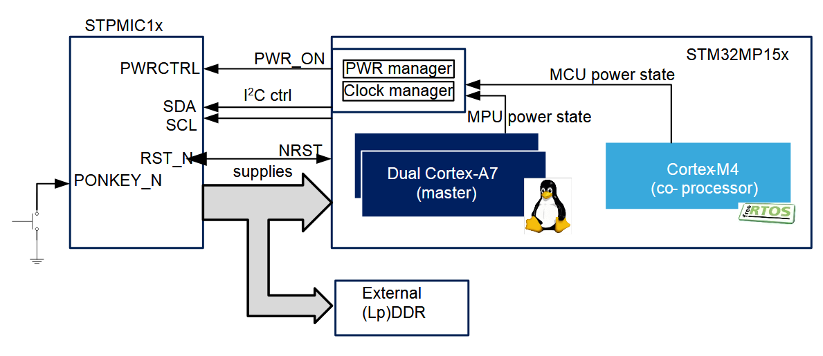
A high-level block diagram of the power system architecture is shown below.
The MPU subsystem and the MCU subsystem can each be in a different power state. There are three power states for the MCU and four power states for the MPU. They are listed in the following table.
| COMPONENT | POWER MODE | DESCRIPTION |
|---|---|---|
| MPU/MCU | CRun | VDD_CORE power ON, Clock ON |
| MPU/MCU | CSleep | VDD_CORE power ON, CPU Clock OFF, Peripheral clock ON/OFF |
| MPU/MCU | CStop | VDD_CORE power ON, CPU Clock OFF |
| MPU | CStandby | VDD_CORE power ON/OFF(¹), Clock OFF |
(1) By default in the OpenST Linux distribution, VDD_CORE is turned OFF during MPU Standby mode. This is configurable.
In addition to the CPU power states, there are also system level power states. The below table shows the mapping between system power states and MPU/MCU power states:
| SYSTEM | MPU | MCU | DDR | OSCILLATORS |
|---|---|---|---|---|
| Run | CRun | CRun/CSleep/CStop | Active/ Auto-refresh | ON |
| CSleep | CRun/CSleep/CStop | |||
| CStop | CRun/CSleep | Self-refresh | ||
| CStandby | CRun/CSleep | |||
| Stop | CStop (PDDS = 0) | CStop (PDDS = 0) | Self-refresh | ON/OFF |
| CStop (PDDS = 1) | ||||
| CStandby | CStop (PDDS = 0) | |||
| LP-Stop | CStop (PDDS = 0) | CStop (PDDS = 0) | Self-refresh | ON/OFF |
| CStop (PDDS = 1) | ||||
| CStandby | CStop (PDDS = 0) | |||
| LPLV-Stop | CStop (PDDS = 0) | CStop (PDDS = 0) | Self-refresh | ON/OFF |
| CStop (PDDS = 1) | ||||
| CStandby | CStop (PDDS = 0) | |||
| Standby | CStop (PDDS = 1 CSTBYDIS = 1) | CStop (PDDS = 1) | OFF/Self-refresh | OFF |
| CStandby | ||||
| VBAT | OFF | OFF | OFF | HSE: OFF LSE: ON |
From the Power State Table, there are three register bits that can control the power states for the MPU/MCU within a system power state. They are listed in the below table along with the settings and corresponding low power modes achievable.
| CSTBYDIS (PWR_MPUCR) | PDDS (PWR_MPUCR) | PDDS (PWR_MCUCR) | SYSTEM OPERATION MODES AVAILABLE |
|---|---|---|---|
| X | 0 | X | Stop, LP-Stop, LPLV-Stop (with MPU in CStop) |
| 0 | 1 | 0 | Stop, LP-Stop, LPLV-Stop (with MPU in CStandby) |
| 0 | 1 | 1 | Standby (with MPU in CStandby) |
| 1 | 1 | 1 | Standby (with MPU in CStop) |
Setting these bits, and by implication the power state of the processor in a given system power state, can be done in “pwr” node of the Linux Device Tree.
To set the voltage rails of the PMIC, the STM32MP15x uses two interfaces to the STPMIC1A:
| CONTROL INTERFACE (STM32MP15x) | PMIC CONNECTION | FUNCTION |
|---|---|---|
| PWR_ON pin | PWRCTRL pin | PMIC power mode control |
| I2C4 interface of STM32MP15x | I2C interface of STPMIC1A | Power rail ON/OFF/level control |
Within Linux, a product can use both interfaces to customize the power rail behavior in the different power states. For example, the VDD_CORE power rail uses both the PWR_ON control pin and the I2C interface to set whether the rail is on or off in the different system power states. The table below shows the PWR_ON levels in the corresponding system power state for the default OpenST Linux distribution.
| OSD32MP15x Power State | PWR_ON | VDD_CORE |
|---|---|---|
| Startup (until VDD reached POR threshold level) | 0 | OFF |
| Run | 1 | ON |
| Stop | 1 | ON |
| LP-Stop | 0 | ON |
| LPLV-Stop | 0 | ON |
| Standby | 0 | OFF |
| VBAT | HiZ | OFF |

As can be seen from the table, the I2C interface is used instead of the PWR_ON signal to modify the state of VDD_CORE in the Standby power state. To modify/shutdown other power rails based on the state of the PWR_ON signal the PREG_MODE and ENA bits of the following registers are used:
| STPMIC1A RESGISTERS | ADDRESS RANGE | PREG_MODE (BIT 1) | ENA (BIT 0) | ||
|---|---|---|---|---|---|
| 0 | 1 | 0 | 1 | ||
| BUCKx_MAIN_CR | 0x20 – 0x23 | High power | Low power | Disabled | Enabled |
| LDOx_MAIN_CR | 0x25 – 0x2A | NA | NA | Disabled | Enabled |
| BUCKx_ALT_CR | 0x30 – 0x33 | High power | Low power | Disabled | Enabled |
| LDOx_ALT_CR | 0x35 – 0x3A | NA | NA | Disabled | Enabled |
| REFDDR_MAIN_CR | 0x24 | NA | NA | Disabled | Enabled |
| REFDDR_ALT_CR | 0x34 | NA | NA | Disabled | Enabled |
The configuration of described hardware architecture and entry/exit configuration for each low power mode can be handled in the OpenST Linux distribution.
Using Power Management under Linux
The infrastructure described in the previous section is used by the Linux Suspend Framework to allow Linux to control the system power states. The following figure shows the power management software framework in Linux.
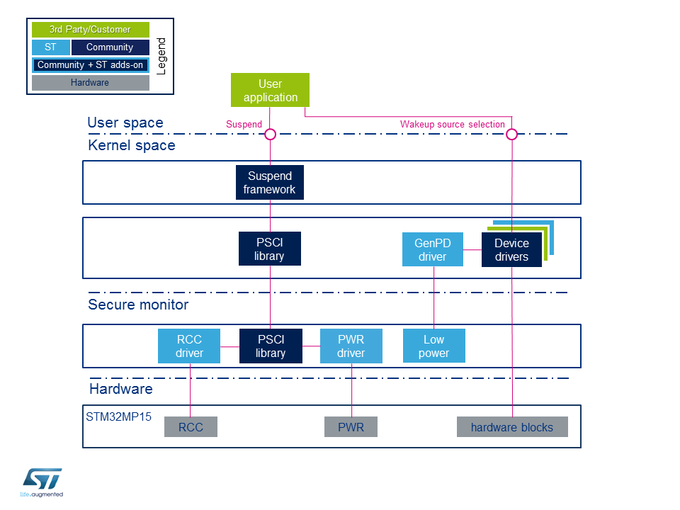
| COMPONENT | FUNCTION |
|---|---|
| Suspend framework | Schedule power state change |
| PSCI library | Standardized function library to request power services in secure monitor |
| GenPD Driver + Low Power Driver | Driver used to select power state according to activated wakeup sources |
| RCC Driver | Driver that handles the secure and non-secure clocks |
| PWR Driver | Driver responsible for configuring power state |
The drivers and features required for transition and management of power states are only available in the Secure monitor CPU operating state. The Secure monitor is implemented in TF-A, which is used as the FSBL (First Stage Bootloader) in the OpenST Linux distribution. The BL32 component of the TF-A or OPTEE can handle the power mode state transitions and PMIC register programming via the Power State Coordination Interface (PSCI). Because the features required to access low power modes are only available in TF-A/OPTEE, only trusted/secure Linux images can be used to support low power modes in target applications.
Entering a Low Power State
There are two distinct ways to initiate a low power state transition depending on which low power state is targeted. The below table shows the two Linux commands and their corresponding low power states.
| COMMAND | STATE |
|---|---|
| shutdown -h 0 | Standby with DDR OFF |
| echo mem > /sys/power/state |
|
Under the hood, the suspend framework notifies all the device drivers to prepare for low power entry and then calls the PSCI service, which then implements the low power mode transition.
The “mem” command can be used to initiate multiple low power states. The state that the system enters is determined by the wake-up source selected. The wakeup sources and their corresponding low power modes are displayed in the following table.
| WAKEUP SOURCE | LINUX COMMAND | SYSTEM LOW POWER MODE | SYSTEM DDR | LINUX KERNEL STATE | POWER CONSUMPTION | WAKEUP TIME | APPLICATION GUIDELINE |
|---|---|---|---|---|---|---|---|
| GROUP 1 | mem | Stop or LP-Stop | Self-refresh | Suspend to ram | Med | Med | PWR_ON pin can be used to set additional power rail activity |
| GROUP 2 | mem | LPLV-Stop | Self-refresh | Suspend to ram | Low | Med | Suitable for applications with aggressive power saving goals |
| GROUP 3 | mem | Standby | Self-refresh | Suspend to ram | Low | Med | Saves more power at expense of wakeup time |
| shutdown | Standby/OFF/ VBAT | OFF | Shutdown | Very low | High |
Each group has different peripherals that can be used as wake up sources from low power states. The table below describes which peripherals belong to each group as well as the low power state from which the peripherals can wake up the system.
| GROUP | WAKEUP SOURCES | WAKEUP LOW POWER STATES |
|---|---|---|
| GROUP 1 | USB, CEC, ETH, USART, I2C, SPI, LPTIM | Stop, LP-Stop |
| GROUP 2 | PVD, AVD, IWDG, GPIO | Stop, LP-Stop, LPLV-Stop |
| GROUP 3 | BOR, VBAT mon, Temp mon, LSE CSS, RTC, TAMP, Wakeup pins | Stop, LP-Stop, LPLV-Stop, Standby, VBAT |
Not all power state transitions are valid from each system power state. The figure below graphically shows the power state transitions that are available at each system power state:
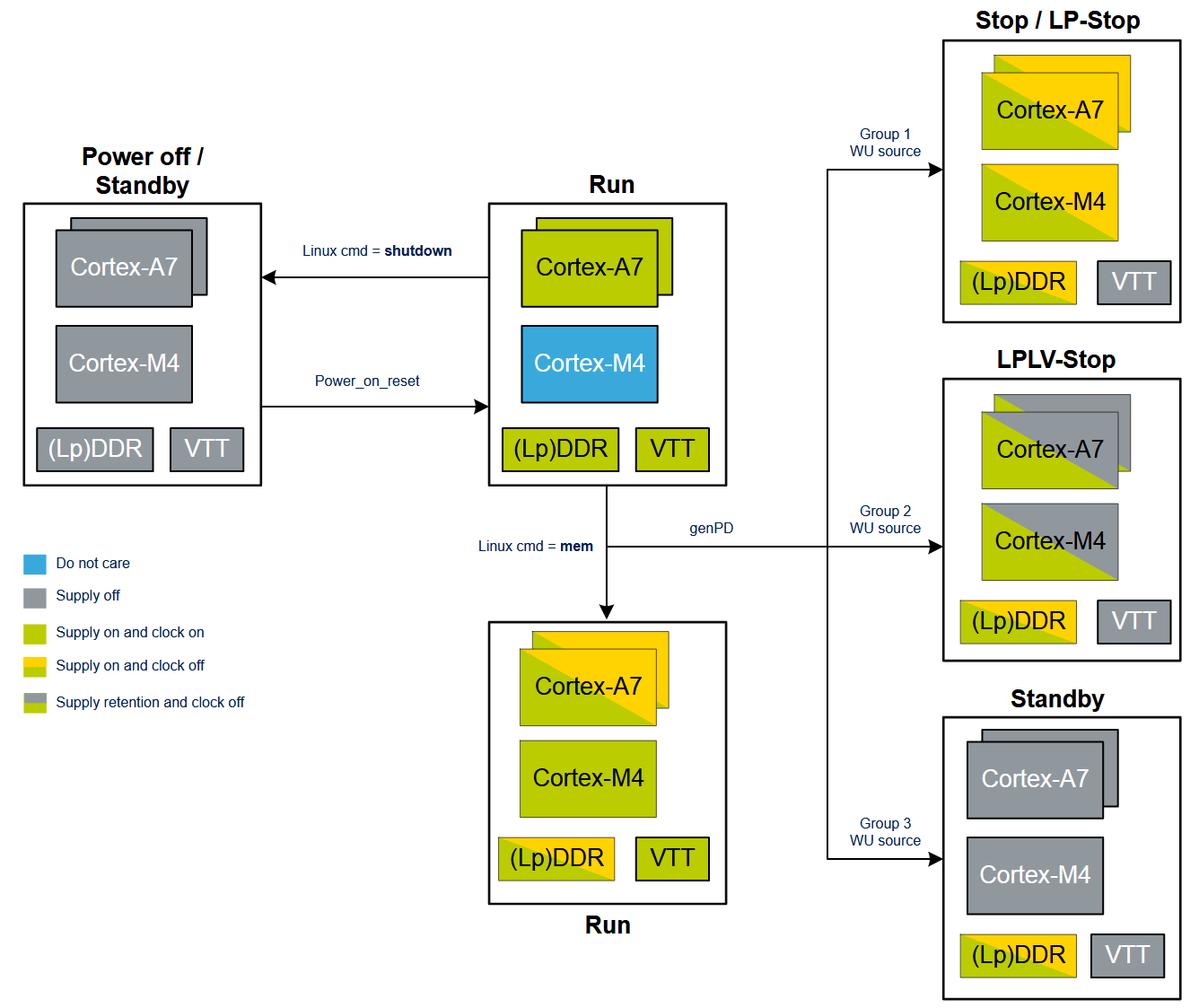
For example, the LP-Stop power state can be achieved by using the following commands with a UART console wakeup source:
- echo enabled > /sys/devices/platform/soc/40010000.serial/tty/ttySTM0/power/wakeup
- echo enabled > /sys/devices/platform/soc/40010000.serial/power/wakeup
- echo mem > /sys/power/state
Commands 1 and 2 are used to set up UART console as the wakeup source. This sets up the device to wake up when there is activity on UART console and resume activity in Run mode. Command 3 activates the entry into low power state.
The power architecture of the OSD32MP15x Family of devices provides a flexible framework to allow a system to achieve many different power states. The different power states provide flexibility when designing and budgeting the power system and understand overall system power consumption, especially in battery operated applications. The OSD32MP1 Power Budgeting App Note describes the power budgeting process necessary to build a robust power system for products / designs.
Conclusion
In conclusion the STM32MP1 and the STMPMIC1 integrated into the OSD32MP1 System-in-Package provide many options for different power modes and states. These different states allow a designer to hone in the power consumption to what is required by their application.
This App note provided an overview of the different low power states and how to configure them. If you have more questions, please ask in our Forums.
Revision History
Want to stay informed about any updates made to this app note? Sign up for our document change update notifications below.
"*" indicates required fields
| Revision Number | Revision Date | Changes | Author |
| 1 | 09/03/2020 | Initial Release | Justin Berry, Neeraj Dantu |
