IoT Gateway and Remote Display Using OSD335x, the AM335x System in Package Family of Devices
Published On: September, 23, 2019 By: Neeraj Dantu
This application note describes how to build an IoT Gateway with a remote display using the OSD335x, the AM335x Family of System-in-Package devices. The IoT sensors described in the application note entitled “Develop the Smallest 1GHz Linux Edge Computing Platform with the AM335x Based OSD335x C-SiP” gather data and communicate it to the IoT gateway. The IoT gateway can optionally perform some local processing on the data to manage information flow before forwarding the information to the cloud or a remote device that can display the information. In the example system described in this application note, the display serves as a human interface that can be useful to monitor and help make key decisions based on the sensor measurements.
Get updates to this application note and all of our technical documentation.
"*" indicates required fields
Table of Contents
1. Introduction to the IoT Gateway Design Using the AM335x Family of System in Package Devices
1.1 IoT Gateway Network Architecture Using an AM335x Based SBC
1.2 Remote Display for the IoT Gateway Using an AM335x Based SBC
2. Setting Up the System
2.1 Hardware Setup
2.2 Software Setup
2.3 IoT Sensor Gateway Application
2.3.1 Compilation
2.3.2 IoT Sensor
2.3.3 IoT Gateway
2.3.4 Remote Display
2.4 Dashboard Application
3. Running the Example IoT System
3.1 Remote Display (OSD3358-SM RED)
3.2 IoT Gateway (BeagleBone® Black Wireless)
3.3 IoT Sensors
4. Conclusion
5.Revision History of this Document
![]()
![]() A PDF version of this App Note can be found HERE
A PDF version of this App Note can be found HERE
![]()
![]() Files associated with this App Note can be downloaded HERE
Files associated with this App Note can be downloaded HERE

1 Introduction to the IoT Gateway Design Using the AM335x Family of System in Package Devices
With the proliferation of IoT (Internet of Things) systems, it is important to be able to aggregate and display the information from all the sensors within the system. The hardware and software developed in this application note will be one piece of a larger project that demonstrates an IoT system using the OSD335x, the AM335x Family of System in Package devices. The IoT system employs a sensor-gateway-display architecture as seen in Figure 1. The hardware developed in this project will have 2 main functions to showcase the data aggregation and display capabilities of OSD335x-BAS and OSD335x-SM devices:
- Aggregate sensor data from a variety of wireless sensors and forward that data over a wired network to a remote network node
- Collect information from an IoT gateway and display the information in an easy-to-consume format
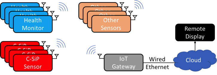

Figure 1 – IoT System with Sensor – Gateway – Remote Display Architecture
The documentation for the Health Monitor Sensor shown in the IoT system has already been published and can be found at:
- Blog: Health Monitor Design with OSD335x SiP
- Hackster.io project: Easy Health Monitor with PocketBeagle®, Click Boards & WiFi
The documentation for the C-SiP Smart Sensor shown in the IoT system has already been published and can be found at:
- Application Note: Develop the Smallest 1GHz Linux Edge Computing Platform with the AM335x Based OSD335x C-SiP
The following sections will describe the IoT Gateway and Remote Display.
1.1 IoT Gateway Network Architecture Using an AM335x Based SBC
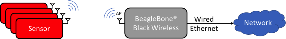
The IoT Gateway acts as a bridge between the wireless network for the sensors and wired network for the infrastructure and serves to aggregate and forward the data from the sensors in the system. In this example system, the BeagleBone® Black Wireless single board computer (SBC) from BeagleBoard.org® will be used as the IoT Gateway.
BeagleBoard.org® , a customer of Octavo Systems, has several SBC boards that are excellent examples of using the OSD335x SiP in a design. The BeagleBone® Black Wireless is great development board to prototype an IoT Gateway. The WL1835 wireless module can act as both an Access Point (AP) as well as a Station (STA). For this example, the wireless module will be configured in AP mode so that all the sensors can connect to the BeagleBone® Black Wireless. Additionally, the Host USB port on the development board can be connected to a USB-to-Ethernet adapter to provide the bridge to the wired Ethernet network. The overall network architecture can be seen in Figure 2
By default, the Access Point has the following network configuration:
| AP Network Name | BeagleBone-XXXX (XXXX is device dependent) |
| Default Password | BeagleBone |
| Default AP IP Address | 192.168.8.1 |
The network will provide the Access Point with an IP address for the egress information traffic, while the AP will provide the connected sensors with IP addresses.
1.2 Remote Display for the IoT Gateway Using an AM335x Based SBC
The Remote Display gathers information from the sensors in the IoT System and presents the information in a clear, easy-to-consume format. This allows humans to make decisions and take action based on the information in the system.
The OSD335x Family of devices provides both an LCD interface that can be use to drive high-resolution displays as well as an Ethernet interface to gather information from networked devices, like an IoT Gateway. For this example IoT system, the OSD3358-SM-RED will be used for the Remote Display as it supports Gigabit Ethernet and a micro HDMI interface.
2. Setting Up the System
This section will discuss the hardware and software required to set up and run the example IoT Gateway and Remote Display demonstration using AM335x based SBCs.
2.1 Hardware Set Up
For simplicity in this demonstration, the network connection between the OSD3358-SM-RED, used for the Remote Display, and the BeagleBone® Black Wireless, used for the IoT Gateway, is a single Ethernet cable. It is easy to see how this could be extended to a more complex network connection where the Remote Display could be physically located far away from the IoT Gateway. Figure 3 shows the connections that need to be made to the OSD3358 SM RED.
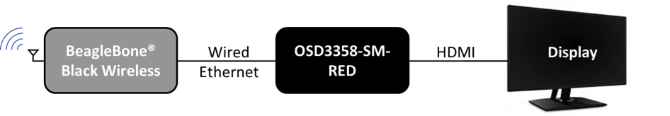
The OSD3358-SM-RED supports gigabit Ethernet for the wired Ethernet connection. However, the OSD3358-SM-RED only supports micro-HDMI so an adapter may be needed to interface with the monitor.
2.2 Software Set Up
There are two software components needed for this example IoT Gateway + Remote Display system.
- IoT Sensor Gateway Application
- Dashboard Application
The IoT Sensor Gateway Application handles the movement of data within the system while the Dashboard Application will display information collected by the IoT system on the Remote Display.
2.3 IoT Sensor Gateway Application
The IoT Sensor Gateway Application has three different data movement tasks:
- IoT Sensor: Transfer data from the IoT Sensors to the IoT Gateway
- IoT Gateway: Forward data from the IoT Sensors to the Remote Display
- Remote Display: Receive data from the IoT Gateway
The ‘Sensor_Gateway’ application found in the project download folder can be used to perform these tasks. It provides a command line interface to transfer a string of data from an IoT Sensor to the IoT Gateway and from the IoT Gateway to the Remote Display. Installation and usage on the devices in the IoT system is described below.
2.3.1 Compilation
After the ‘Sensor_Gateway.tar.gz’ file is copied on the target component, the file can be uncompressed using the following command:
1 | $ tar -xzf Sensor_Gateway.tar.gz |
This command will extract the files into the “Sensor_Gateway” folder. The code can be compiled using the following commands:
1 2 3 | $ cd Sensor_Gateway/ $ sudo make clean $ sudo make all |
2.3.2 IoT Sensor
The ‘msg_client’ application can be used to transfer data from an IoT Sensor to an IoT Gateway. To run the application, the IP address and port number of the IoT Gateway needs to be provided. Below is an example invocation:
1 | $ ./msg_client GW_IP_ADDR GW_PORT <DATA_STRING> |
The <DATA_STRING> in the above command will be transferred to the IoT Gateway. The information contained within the string can be based on the type of data the sensor is sending. Additionally, it can contain identifying information for the sensor. For example, the information from a health monitor sensor can have the following format, where “HMx” is the sensor identifier:
1 | HMx [heart_rate] [temperature] [pressure] |
2.3.3 IoT Gateway
The ‘gw_server’ application can be used to receive information from the IoT Sensors and forward it to the Remote Display. To run the application, the IP address and port of the Remote Display needs to be provided. Additionally, the port number for the IoT Gateway to receive information from the IoT Sensors needs to be provided. This port number should be identical to the port number used by the IoT Sensors in the above ‘msg_client’ command. Below is an example invocation:
1 | $ ./gw_server GW_PORT DISPLAY_IP DISPLAY_PORT |
2.3.4 Remote Display
The ‘ui_server’ application can be used to receive information from the IoT Gateway and store it in a local file. To run the application, the data storage file needs to be provided. Additionally, the port number for the Remote Display to receive information from the IoT Gateway needs to be provided. This port number should be identical to the port number used by the IoT Gateway in the above ‘gw_server’ command. Below is an example invocation:
1 | $ ./ui_server DISPLAY_PORT > /var/lib/cloud9/data_stream.txt |
The file “/var/lib/cloud9/data_stream.txt” is hard coded in the Dashboard Application and must be changed both in the command above and in the Dashboard Application.
2.4 Dashboard Application
To create a Dashboard Application, there are many existing graphical frameworks available that can ease implementation and shorten development time. This example uses the Smashing framework to create the Dashboard Application. More information on the Smashing framework can be found at: https://smashing.github.io
The example Dashboard Application utilizes the following features of the framework:
- Customizable premade display widgets
- Ruby scripting interface for fetching and pushing information to the dashboard
- Web hosting and access to the dashboard via web browser
The following commands are needed to install the required packages and setup the Smashing framework on the OSD3358-SM-RED. Note that the OSD3358-SM-RED will need to be connected to the internet during this installation.
1 2 3 4 5 6 | $ sudo apt-get update $ sudo apt-get install ruby $ sudo apt-get install ruby-dev $ sudo apt-get install bundler $ sudo gem install smashing $ sudo gem update --system |
Once the required packages are installed, the Smashing project ‘IOT_Display.tar.gz’ can be uploaded to the OSD3358-SM-RED and started with the following commands:
1 2 3 4 | $ tar xzf IOT_Display.tar.gz $ touch /var/lib/cloud9/data_stream.txt $ cd IOT_Display $ smashing start |
The file “/var/lib/cloud9/data_stream.txt” is hard coded within the project and is necessary for the project to run. The information in the file will be parsed to update the information on the dashboard.
The dashboard can be viewed on the Remote Display by using a web browser and navigating to the following web address:
1 | http://localhost:3030 |
Beyond having in the information displayed on an attached monitor, the Smashing framework also allows for the dashboard to be viewed remotely by computers on the same network. To view the dashboard on another device on the same network via web browser, please use the following web address:
1 | http://OSD3358-SM-RED_IP_ADDR:3030 |
You will need to know the IP address of the OSD3358-SM-RED that is being used as the Remote Display in order to view the dashboard. You can find this information using Linux commands such as ‘ifconfig’.
3 Running the Example IoT System
This section consolidates the information needed to set up and run the example IoT System that has been described in this application note. It is divided in to the steps needed for each of the components in the system.
3.1 Remote Display (OSD3358-SM RED)
The following procedure describes the setup of the Remote Display:
- Connect OSD3358-SM-RED to a monitor via HDMI
- Connect an Ethernet cable to OSD3358-SM-RED Ethernet interface
- Boot the OSD3358-SM-RED
- Record the IP address of the OSD3358-SM-RED using a utility like ‘ifconfig’
- Upload the IoT Sensor Gateway Application software ‘tar.gz’
- Upload the Dashboard application software ‘tar.gz’
- Un-compress and compile the gateway application as shown in Section 2.3.1
- Start the UI Server by using the command in Section 2.3.4. Any open port can be used for the DISPLAY_PORT. Make note of this port for IoT Gateway setup.
- Install Smashing framework and start Dashboard Application as described in Section 2.4
- Open the Chromium browser and launch the Dashboard Application by using the web address: http://localhost:3030
3.2 IoT Gateway (BeagleBone® Black Wireless)
The following procedure describes the setup of the IoT Gateway:
- Connect a USB-to-Ethernet adapter to the USB port of the IoT Gateway
- Connect an Ethernet cable to the USB-to-Ethernet adapter. You should not need a special cross-over Ethernet cable since the Ethernet PHYs should be capable of auto-negotiation
- Boot the BeagleBone® Black Wireless
- Connect to the IoT Gateway via the WiFi Access Point
- Upload the IoT Sensor Gateway Application software ‘tar.gz’
- Un-compress and compile the gateway application as shown in Section 2.3.1
- Start the IoT Gateway Server by using the commands in Section 2.3.3. Any open port can be used for the GW_PORT. The DISPLAY_IP and DISPLAY_PORT are the IP address of the OSD3358-SM-RED recorded above and the DISPLAY_PORT for the Remote Display.
The BeagleBone® Black Wireless will automatically start a WiFi Access Point on boot.
3.3 IoT Sensors
This example system uses two IoT Sensors:
- PocketBeagle® Health Monitor
- C-SiP IoT Sensor
The sensors relay the following data to the gateway:
| Sensor | Data |
| PocketBeagle® Health Monitor | Heart Rate, Temperature, and Pressure |
| C-SiP IoT Sensor | Light, Proximity, and Accelerometer |
The hardware and software setup for both these sensors is described in the following application notes:
- Health Monitor Design with OSD335x SiP (using BeagleBoard.org® PocketBeagle®)
- Develop the Smallest 1GHz Linux Edge Computing Platform with the AM335x Based OSD335x C-SiP
Before starting the information collection application that uses the IoT Gateway Sensor Application, the sensor needs to be connected to the IoT Gateway.
4 Conclusion
This demonstration shows how the OSD335x Family of devices can be used in the different roles in an IoT system; either as an edge processing device, an IoT Gateway, or a Remote Display. Because of the flexibility and compute power provided by the 1GHz Arm Cortex™ A8 processor, the different peripheral interfaces provided by the AM335x SoC, and the vast array of open source resources for building IoT applications, building and customizing IoT systems becomes very easy. Additionally, the design and manufacturing benefits of the OSD335x Family of devices means that there is only one question left to answer: When are you going to get started building your own IoT System?
5 Revision History
| Revision Number | Revision Date | Changes | Author |
|---|---|---|---|
| 1 | 9/1/2019 | Initial Release | N. Dantu |
