gil_he
Forum Replies Created
-
AuthorPosts
-
hello Neeraj,
I’ve taken a correct CubeProgrammer sequence (from https://community.st.com/s/question/0D53W000007Y3WmSAK/using-stm32cubeprogrammer-v220-to-program-sd-card-of-our-board-the-board-is-base-on-stm32mp157cdk2-but-fail-and-get-error-messageerror-start-operation-failed-at-partition-0x01error-tsv-flashing-service-failed)
and compared to AN5275, figure 3, page 6.I think, we passed the “Authenticate and start TF-A (in SYSRAM)”, so it seems our USBC port is configured as required (TF-A load is successful).
So, we are in either “Get boot config from BootRom” or “init clock and DDR” states.
Do you agree?
(I do not think we reached the “FlashLayout & start” state).What can cause our start operation to fail?
Is it the files used to create the tf-a.stm32 binary?
Maybe the clock configuration tree?
Also:
The GenerateCode of the CubeMx gave us three files (under the TF-A folder):
stm32mp157c-lucid40_p1-mx-fw-config.dts
stm32mp157c-lucid40_p1-mx.dts
stm32mp15-mx.dtsiThe file, stm32mp157c-lucid40_p1-mx-fw-config.dts, has an include to a dtsi file which we don’t have.
It has only these two lines:
#define DDR_SIZE 0x20000000 /* 512MB */
#include “stm32mp15-fw-config.dtsi”Should we rename the include to “stm32mp15-mx.dtsi”?
thanks
Gil
January 12, 2023 at 6:08 am in reply to: STLINK-V3SET connection to OSD32MP157C using CubeProgrammer #13273hello Neeraj,
I was able to connect the RED to the debugger using SWD.
I need to perform some wire stitching before I can connect our board to the debugger using SWD.
My question:
Can we use the CubeIDE to debug the FSBL load/run process via SWD connection?
Can you guide me on what should be done?
thanks
Gil
-
This reply was modified 2 years, 4 months ago by
gil_he.
hello Neeraj,
I have gone through the article you sent.
It talks about the UBOOT (partition 3) which disconnects/re-initializes the USB and that may cause a reconnect to fail.
Does the FSBL (partition 1) also acts like that?
In my design, OTG_VBUS is connected to the VBUS pins of the USB3 type C connector we have in the board (we use it as USB2), so it gets the 5v from there.
The OpenSTLinux version we use is “dunfell”. I installed the latest V2.12.0 CubeProgrammer.
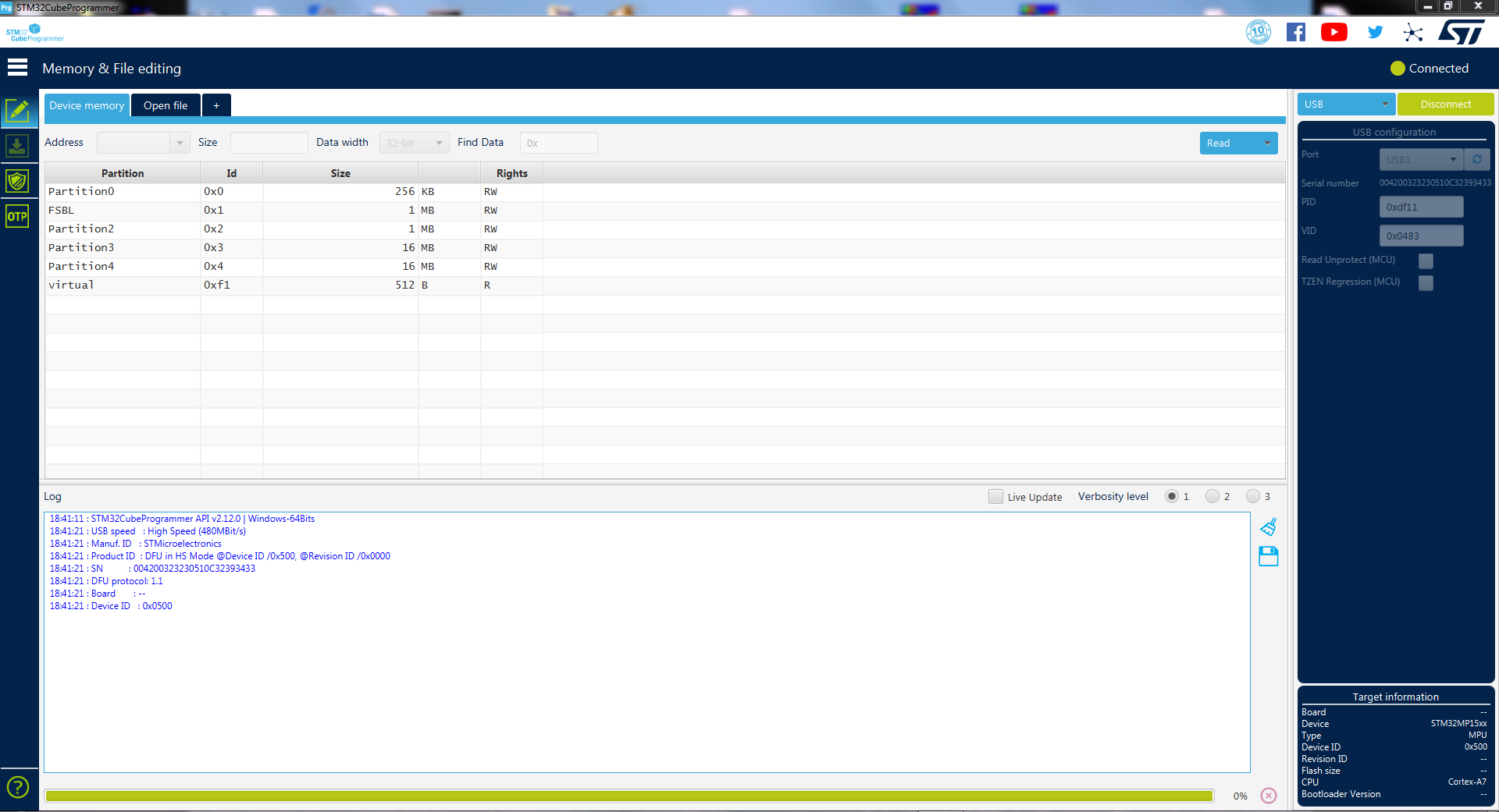
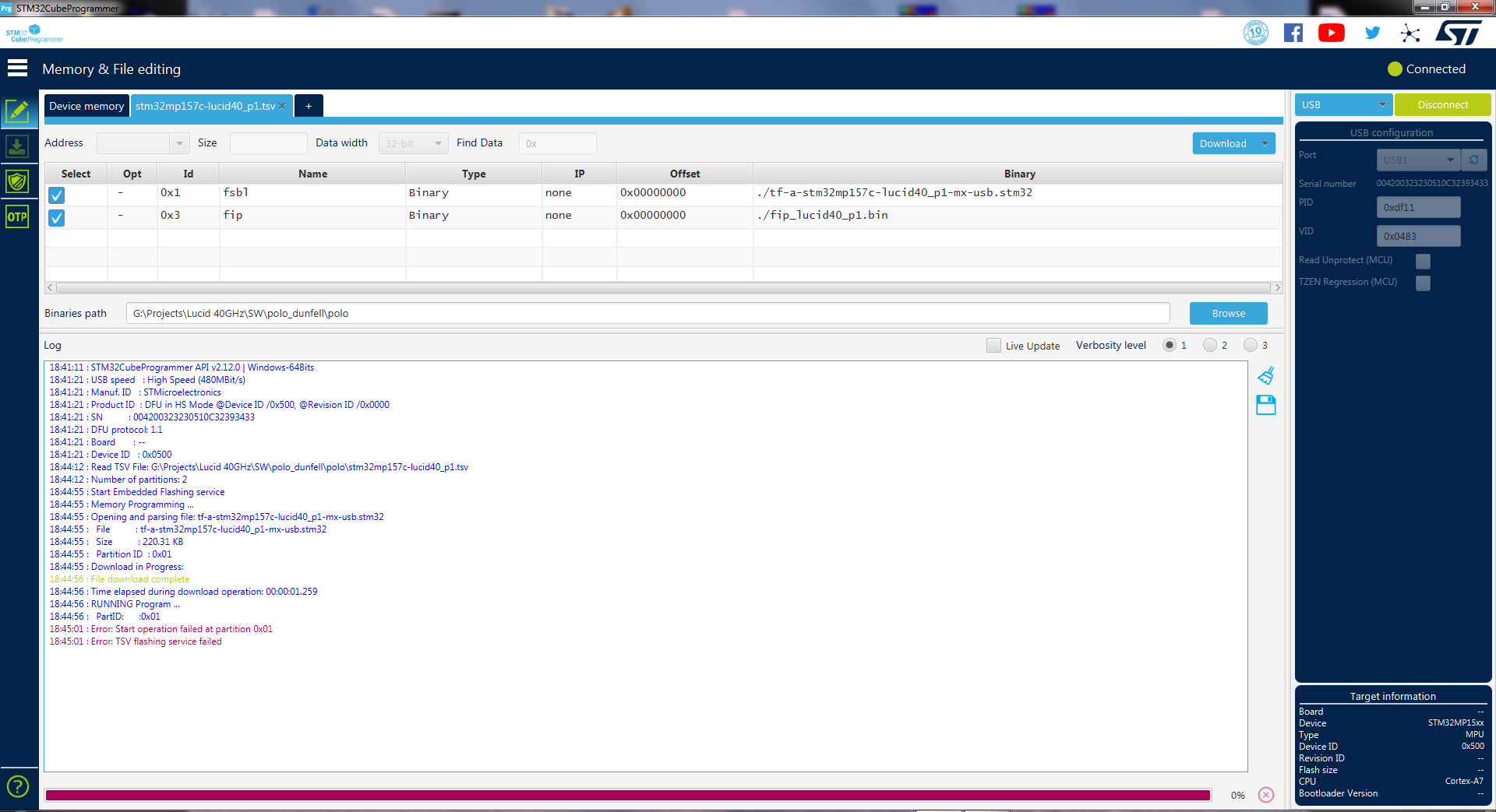
Find enclosed the output of the CubeProgrammer during download (first pic is after connection. 2nd is after downloading).
We don’t have working UART port so cannot send the output on the console for the board (we will have UART only after UBOOT loads and we change pin muxing).
thanks
Gil
January 6, 2023 at 5:46 am in reply to: STLINK-V3SET connection to OSD32MP157C using CubeProgrammer #13049hello Neeraj,
I verified your comments.All is, as required.
I am using STM32cubeProgrammer as stand-alone (not part of CubeIDE).
Installed the latest software. I hope it installs the latest drivers.
Still, no response from the debugger.
We don’t have a ST EV1.
Can you verify the RED and STLINK-V3 communicate in your lab?
In our lab they don’t.
I compared the signals the debugger send to the RED and to our project. They are very much alike.
J_TDO has no activity.
thanks
Gil
-
This reply was modified 2 years, 4 months ago by
January 5, 2023 at 9:00 am in reply to: STLINK-V3SET connection to OSD32MP157C using CubeProgrammer #13043An update:
I connected the debugger (STLINK-V3SET) to the Octavo RED.Also added the NRST and NJRST signals from the RED to the Debugger (pins 12 and 11 respectively).
Still, no response.
The CubeProgrammer doesn’t recognize the Octavo SiP.
-
This reply was modified 2 years, 4 months ago by
hello Michal,
Thank you for a detailed reply.
We still don’t have Linux and UBOOT.
We want to know if there is a way to program the FSBL only to the eMMC given we don’t have the SSBL and Linux.
Our board is in bring-up stage.
thanks
Gil
hello Neeraj,
Are the solder bumps (solder balls) on the OSD32 Pb Free?
Should we use a Pb Free or SnPb reflow profile?
I understand the Peak temperature is package dependent.
Can you send a recommended reflow profile for the OSD32?
thanks
Gil
-
This reply was modified 2 years, 8 months ago by
Hi Michal,
Do you recommend using the reflow profile you sent for soldering a new OSD32?
thanks
Gil
Hi mwlinux,,
We sent the board for a selective reflow replacement of some other device, and the board came back with the OSD32 defective.
The PMIC_BUCK4 gives a wrong voltage (very low).
I wonder if the replacement process somehow damaged the OSD32.
So, we want to remove the defective OSD32 and place a new OSD32 instead.
I understand the difficulties you mentioned are with regard to assembly of a used device, not a new one. Is that correct?
So, we don’t need any reballing.
Take the stencil we have, take a new OSD32 out of the bag, bake it (or not) and assemble according to the reflow you posted.
Am I correct here?
Do we also risk the 5V to GND shortcuts?
Thank you,
Gil
hello,
An update:
This will be a selective reflow process (replacing only the device and not a reflow of the entire pcb).
Is the soldering profile different than the one for a full pcb reflow?
thanks,
Gil
hello Neeraj,
I connected the I2C port of the PMIC in our board (Pz4, Pz5 in the Octavo) to the Octavo RED evb to JP20, pins 3,5,6, which connect to I2C5 of the Octavo in the RED evb.
Our board is not running any code. Power-up and that’s it (no FSBL, SSBL, etc.).
We connected to the RED evb using SSH (to the IP of the RED). We used the I2C tools to detect and dump the registers of the I2C devices.
I was unable to read anything from the PMIC. Not from the faulty SiP (wrong PMIC_VOUT4) and not from a working SiP.
I2C detect did not find any slave devices on this bus. Then, I specifically searched for I2C address 0x33. Nothing there.
What was I doing wrong?
thanks
Gil
hello Neeraj,
I am re-opening this thread.
You wrote we can program the PMIC NVM using the STM32CubeProgrammer.
We ran the programmer (connected to the board via USB) and I did not find the PMIC NVM partition (identified by the reserved Id 0xF4).
Documentation states it is supported only in U-BOOT and since we are in the SiP boot stage (no FSBL, SSBL, etc), I guess we cannot see it.
Is there any other way I can view the PMIC NVM and program it? (besides using the M4).
I understand JTAG cannot help us here.
I2C perhaps? If yes, using which software?
This is my 1st question.
2nd Q: The reason I am asked the 1st Q, is that PMIC_VOUT4 outputs the wrong voltage in one of our boards (it worked fine and suddenly something changed).
I would like to see whether, somehow, the PMIC NVM changed its content, thus a different voltage on PMIC_VOUT4.
Is anything like this happened to you?
Adding to that:
If a voltage is forced on PMIC_VOUt4 output before it is regulated (2.5V from another source): can it damage the PMIC_VOUT4 output stage?
thanks,
Gil
Hi Neeraj,
The design is over. For the current board revision.
SDMMC2_D4 is routed to PA8.
If I do not need this functionality, can I use the USBS interface without any issues?
There is no SOF pin on the USBC connector. Does a design that do use this functionality, need to route some signal to this pin? (internally in the board).
thanks,
Gil
hello Neeraj,
In addition to the above:
It seems there is an issue with PA8 I chose for SDMMC2_D4.
When choosing PB8 or PE4 the conflict is not there.
PA8 also occupies the role of OTG_HS_SOF.
If PA8 is used as SDMMC2_D4, OTG_HS_SOF cannot be asserted externally.
However, internally, this token can be used and is used as part of the protocol.
Am I correct with all that I wrote?
Will we have an issue with our USB interface?
thanks,
Gil
-
This reply was modified 2 years, 10 months ago by
-
This reply was modified 2 years, 4 months ago by
-
AuthorPosts


