Routing eMMC signals for OSD335x-SM: Follow RED board layout or apply length mat
Forums › Reference, Evaluation, and Development Boards › OSD3358-SM-RED › Routing eMMC signals for OSD335x-SM: Follow RED board layout or apply length mat
Tagged: emmc length matching
- This topic has 3 replies, 2 voices, and was last updated 1 month, 2 weeks ago by
 Neeraj Kumar Reddy Dantu.
-
AuthorPosts
-
-
April 11, 2025 at 8:50 am #15878
<p class=”” data-start=”313″ data-end=”316″>Hi,
<p class=”” data-start=”318″ data-end=”493″>I’m currently designing a custom PCB using the <strong data-start=”365″ data-end=”383″>OSD3358-SM SiP, and I’m closely following the schematic and layout of the <strong data-start=”443″ data-end=”461″>OSD3358-SM-RED development board as reference.
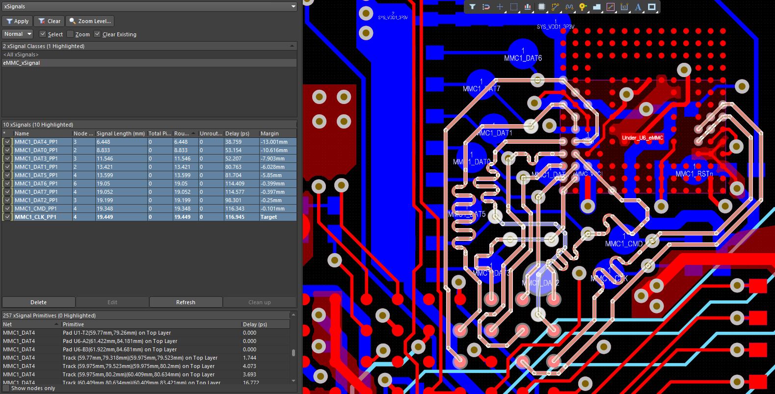
<p class=”” data-start=”495″ data-end=”762″>While reviewing the layout—specifically the routing between the <strong data-start=”559″ data-end=”573″>OSD335x-SM and the <strong data-start=”582″ data-end=”590″>eMMC—I noticed that the <strong data-start=”610″ data-end=”653″>control and data lines (DATx, CMD, CLK) do not appear to be length-matched according to standard high-speed design practices (e.g., within ±0.5?mm).
<p class=”” data-start=”764″ data-end=”959″>I’m aware that eMMC communication at <strong data-start=”801″ data-end=”824″>High Speed (52?MHz) or higher typically requires equal trace lengths for reliable signal integrity, especially between <code data-start=”924″ data-end=”929″>CLK, <code data-start=”931″ data-end=”936″>CMD, and the <code data-start=”946″ data-end=”952″>DATx lines.
<p class=”” data-start=”961″ data-end=”985″>So I have two questions:-
<li class=”” data-start=”987″ data-end=”1106″>
<p class=”” data-start=”990″ data-end=”1106″><strong data-start=”990″ data-end=”1036″>Should I trust the layout of the RED board, even though it doesn’t seem to apply length matching for eMMC lines?<li class=”” data-start=”1107″ data-end=”1221″>
<p class=”” data-start=”1110″ data-end=”1221″>Or, should I define a <strong data-start=”1132″ data-end=”1156″>length-matching rule in Altium and apply tuning to all eMMC nets in my custom layout?<p class=”” data-start=”1223″ data-end=”1427″>Any advice on whether the RED board layout has been tested/validated with relaxed length matching for eMMC would be greatly appreciated. I want to make sure my design is robust and follows best practices.
<p class=”” data-start=”1429″ data-end=”1447″>Thanks in advance!
<p class=”” data-start=”1449″ data-end=”1476″>Best regards
Attachments:
-
April 11, 2025 at 8:52 am #15880
Thanks
-
April 11, 2025 at 8:52 am #15881
I’m currently designing a custom PCB using the OSD3358-SM SiP, and I’m closely following the schematic and layout of the OSD3358-SM-RED development board as reference.
While reviewing the layout—specifically the routing between the OSD335x-SM and the eMMC—I noticed that the control and data lines (DATx, CMD, CLK) do not appear to be length-matched according to standard high-speed design practices (e.g., within ±0.5?mm).
I’m aware that eMMC communication at High Speed (52?MHz) or higher typically requires equal trace lengths for reliable signal integrity, especially between CLK, CMD, and the DATx lines.
So I have two questions:
Should I trust the layout of the RED board, even though it doesn’t seem to apply length matching for eMMC lines?
Or, should I define a length-matching rule in Altium and apply tuning to all eMMC nets in my custom layout?
Any advice on whether the RED board layout has been tested/validated with relaxed length matching for eMMC would be greatly appreciated. I want to make sure my design is robust and follows best practices.
Thanks in advance!
Best regards,
-
April 14, 2025 at 4:35 pm #15883
Antonio,
In addition to signal speed of 52MHz, trace length matching depends on other factors that have to do with the physical transmission medium and how it effects propagation delay.
Back of the napkin calculation for a 52MHz signal:
Period of signal is 1/52MHz = ~20ns. If you want to keep delay to ~5% of this period = ~1ns. Assuming that the transmission delay of the PCB is ~6 inches/ns(this can vary from PCB to PCB), the maximum difference in traces can be ~6 inches.
We never want to be this close. With 5mm difference you see on MP1-RED, there should be no issue.
However, there are other factors to consider:
– Do you plan to use high speed modes of the MMC controller running in DDR mode at 100MHz(~200MHz)? If so, the length matching rules will need to be tighter.
– Consider also that propagation delay is based on PCB parameters.
– We did not consider setup and hold times in the above calculation.
– eMMC being used might have special delaysMy recommendation is to be as close as possible in matching as it would not hurt to make it tighter. The MP1-RED was designed keeping the use case(52MHz max) and PCB material in mind.
Best,
Neeraj
-
-
AuthorPosts

- You must be logged in to reply to this topic.