Device tree Pinmux for MMC0 in refdesign dts
Forums › Reference, Evaluation, and Development Boards › OSD3358-SM-RED › Device tree Pinmux for MMC0 in refdesign dts
Tagged: csip, device trees, red
- AuthorPosts
- January 4, 2021 at 12:32 pm #11097
 ryanclemParticipant
I’m in the process of developing a custom board based heavily on the osd3358-sm-red platform. I downloaded the device-tree files and think I’ve made good progress in understanding how everything is configured, however there’s one area where I’m still unclear.
The osd3358-bsm-refdesign.dts explicitly sets the pinmux for everything it seems to be using except for the chip’s MMC0 peripheral, which is aliased as &mmc1 in the device tree file. Here it references &mmc1_pins for the pinctrl but that only defines the MUX for a single pin (the card-detect pin):
—-
mmc1_pins: pinmux_mmc1_pins {
pinctrl-single,pins = <
AM33XX_IOPAD(0x960, PIN_INPUT | MUX_MODE7) /* GPIO0_6 */
>;
};
—-In contrast, the &emmc_pins pinctrl lists out all the pins associated with the MMC operation:
—-
emmc_pins: pinmux_emmc_pins {
pinctrl-single,pins = <
AM33XX_IOPAD(0x880, PIN_INPUT_PULLUP | MUX_MODE2) /* gpmc_csn1.mmc1_clk */
AM33XX_IOPAD(0x884, PIN_INPUT_PULLUP | MUX_MODE2) /* gpmc_csn2.mmc1_cmd */
AM33XX_IOPAD(0x800, PIN_INPUT_PULLUP | MUX_MODE1) /* gpmc_ad0.mmc1_dat0 */
AM33XX_IOPAD(0x804, PIN_INPUT_PULLUP | MUX_MODE1) /* gpmc_ad1.mmc1_dat1 */
AM33XX_IOPAD(0x808, PIN_INPUT_PULLUP | MUX_MODE1) /* gpmc_ad2.mmc1_dat2 */
AM33XX_IOPAD(0x80c, PIN_INPUT_PULLUP | MUX_MODE1) /* gpmc_ad3.mmc1_dat3 */
AM33XX_IOPAD(0x810, PIN_INPUT_PULLUP | MUX_MODE1) /* gpmc_ad4.mmc1_dat4 */
AM33XX_IOPAD(0x814, PIN_INPUT_PULLUP | MUX_MODE1) /* gpmc_ad5.mmc1_dat5 */
AM33XX_IOPAD(0x818, PIN_INPUT_PULLUP | MUX_MODE1) /* gpmc_ad6.mmc1_dat6 */
AM33XX_IOPAD(0x81c, PIN_INPUT_PULLUP | MUX_MODE1) /* gpmc_ad7.mmc1_dat7 */
>;
};
—-Looking at the TI pinmux tool and beagle-bone-black dts it appears that for the pins used for MMCO their mux is MUX_MODE0. I’m assuming this is the default mode for the pins? Is that why it’s not needed to be explicitly defined in the &mmc1_pins pinctrl? Would it hurt to explicitly define it anyway for clarity?
Thank you for your clarification!
- This topic was modified 3 years, 3 months ago by
 ryanclem.
- This topic was modified 3 years, 3 months ago by
- January 8, 2021 at 5:05 pm #11107
 Eshtaartha BasuModerator
Hello ryanclem,
The pinmux for MMC0 interface is initialized in U-Boot under mux.c file – https://github.com/RobertCNelson/u-boot/blob/master/board/ti/am335x/mux.c. This should be sufficient.
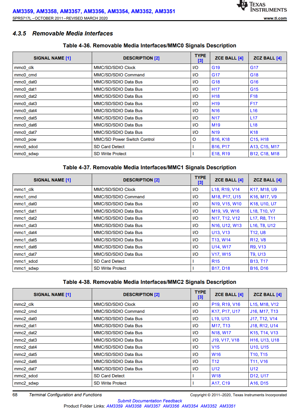
Neither TI nor Beagleboard community reinitialize MMC0 again as part of their Linux device trees. Octavo System’s device trees for OSD3358-SM-RED are based on device trees developed by TI for the AM335x processor. Also, as listed under Tables 4-36, 4-37 and 4-38 of AM335x datasheet (https://www.ti.com/lit/ds/symlink/am3354.pdf?ts=1609958701723&ref_url=https%253A%252F%252Fwww.google.com%252F), MMC0 peripheral can claim only one set of pins when enabled whereas MMC1 and MMC2 interfaces can choose from several sets of pins.
We have not tested the behavior OSD335x with MMC0 pinmux reinitialized as part of Linux DT.
Discussion on the same matter can also be found on TI’s official forum below:
https://e2e.ti.com/support/processors/f/791/t/668324
https://e2e.ti.com/support/processors/f/791/t/758096?Linux-PROCESSOR-SDK-AM335X-Conversion-pinmux-tool-output-to-mux-c-for-u-boot (See Brad’s response at the end)
https://e2e.ti.com/support/processors/f/791/t/742464?AM3356-Configuration-of-MMC0-pins-to-GPIO-mode
- This reply was modified 3 years, 3 months ago by Eshtaartha Basu.
Attachments:
- This reply was modified 3 years, 3 months ago by
- January 13, 2021 at 1:38 pm #11121ryanclemParticipant
Very clear! Thank you for the detailed response.
- AuthorPosts
- You must be logged in to reply to this topic.
