Boot up issue on new revision custom board
Forums › Devices › OSD335x-SM › Boot up issue on new revision custom board
- AuthorPosts
- October 16, 2019 at 4:15 pm #9243
 mnagibullaParticipant
I have an OSD3358-512M-ISM custom board that we are on a 3rd revision. On this 3rd revision I am having issue with boot up. The first two boards had no problem with boot up and this was only introduced in this revision. I have attached revision 2 schematic also.
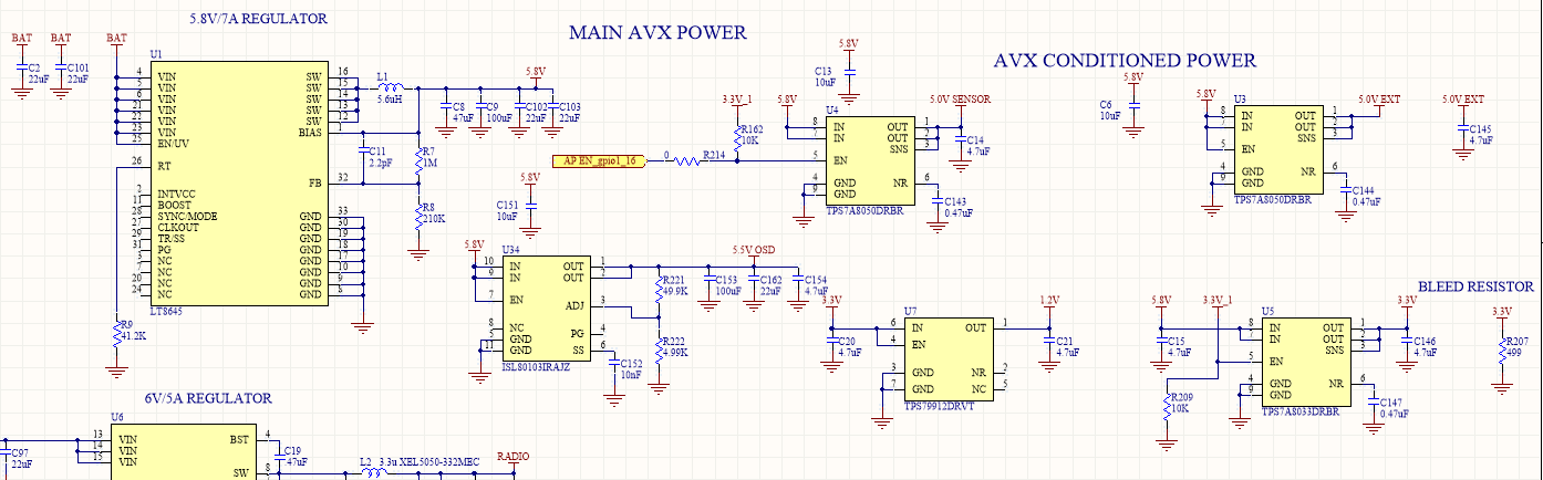
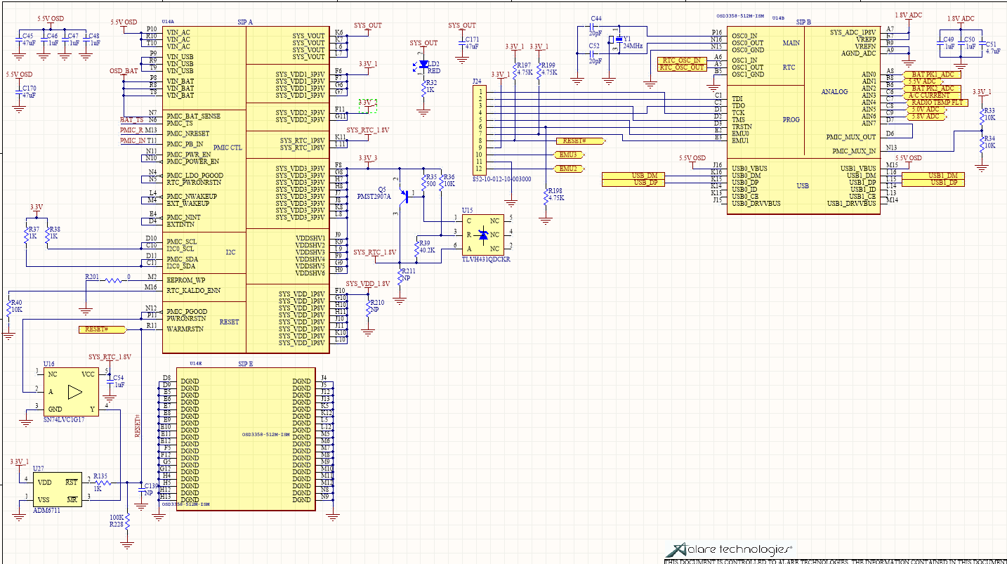
I have attached the schematic of the relevant part of OSD power called Sheet 3 & Sheet 4 for rev 3.
The issue is when powering up the board for the first time, we noticed that we were not getting any CCC’s through the debug serial port. We thought it might be the buffer, however, when we probed it we didn’t see any data coming through. Also the SD Card clock line was not outputting anything. However, all the power supplies that the OSD generates (3.3V_1, 3.3V_2, 3.3V_3, SYS_VDD_1.8) are all up. Also PMIC_PGOOD was high.
We found that when we hold PMIC_PGOOD to ground for longer period of time (around 500mS, while the usually time from power up is around 50mS+) we can get the OSD to boot and output CCC and we were able to flash the OS. However, when we turn off the board and turn it back on it doesn’t come back up and just draws a steady current (125mA at 15V input to power supplies), unless we drive PMIC_PGOOD to ground again.
The only change we did from the last revision of the board is that we are feeding power from and LDO and not a buck converter. We did remove the LDO and fed it directly to 5.5V of the buck converter but that didn’t change anything.
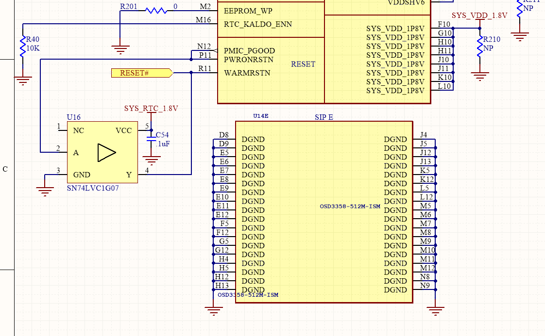
We went ahead and removed the supervisor circuitry and replaced the SN74L-g17 version with the g07 version like what is in the red card. We connected the Y output of the open drain buffer to R135. We basically replicated the exact circuit that was suggested here https://octavosystems.com/app_notes/osd335x-schematic-checklist-am335x/#_Toc382081437 under reset circuit Case 1. We have also tried adding a pull up to 3.3V_1 on the reset with the current configuration and that didn’t really do anything. I have attached a schematic of what it looks like now named reworked rev 3.
After the changes, the OSD still will not come up unless I pull down PMIC_PGOOD or I pull down PMIC_NRESET. However, I can hold down PMIC_PGOOD as I am powering up and letting it go will start the board normal, however, if I do the same thing with PMIC_NRESET it will not work. I have to boot up the board first then pull down PMIC_NRESET for the OSD to come up.
As for our last revision board (rev 2), we didn’t change anything major. This is the exact same parts we have used in both boards. The only thing that we think might cause issues but we are not sure about is the 5.5V_OSD that is connected to USB0_VBUS and USB1_VBUS, that is the only one that we can’t really do much with since we have no access to those pins.
On this current revision we also added a temp sensor that is connected to I2C and a accelerometer that is connected using SPI. However, I measured the pins on those chips and they are not outputting anything on boot up.
I have also measured the power supplies referenced to PMIC_GOOD, and it seems like they all come up before PMIC_GOOD get released. I have checked 3.3V_1, 3.3V_2, 3.3V_3, SYS_RTC_1.8V & SYS_VDD_1.8V.
Any thoughts would be appreciated it.
- October 21, 2019 at 12:21 pm #9257
 Neeraj DantuModerator
Mnagibulla,
We apologize for the delayed response. Can you please check when the 24HMz clock signal comes up in relation to the power rails? We suspect a delay in the clock signal could be holding up the processor from booting.
Another thing to check is the boot mode configuration(See Table 26-7 of the AM335x Technical Reference Manual: https://www.ti.com/lit/ug/spruh73p/spruh73p.pdf) The device may be getting ‘stuck’ in a boot source that has precedence over UART/MMC. If you can, please verify the SYSBOOT configuration and post here.
Please let us know how the debug is going and if you have additional questions.
Best,
Neeraj.
- October 21, 2019 at 4:12 pm #9268mnagibullaParticipant
Neeraj,
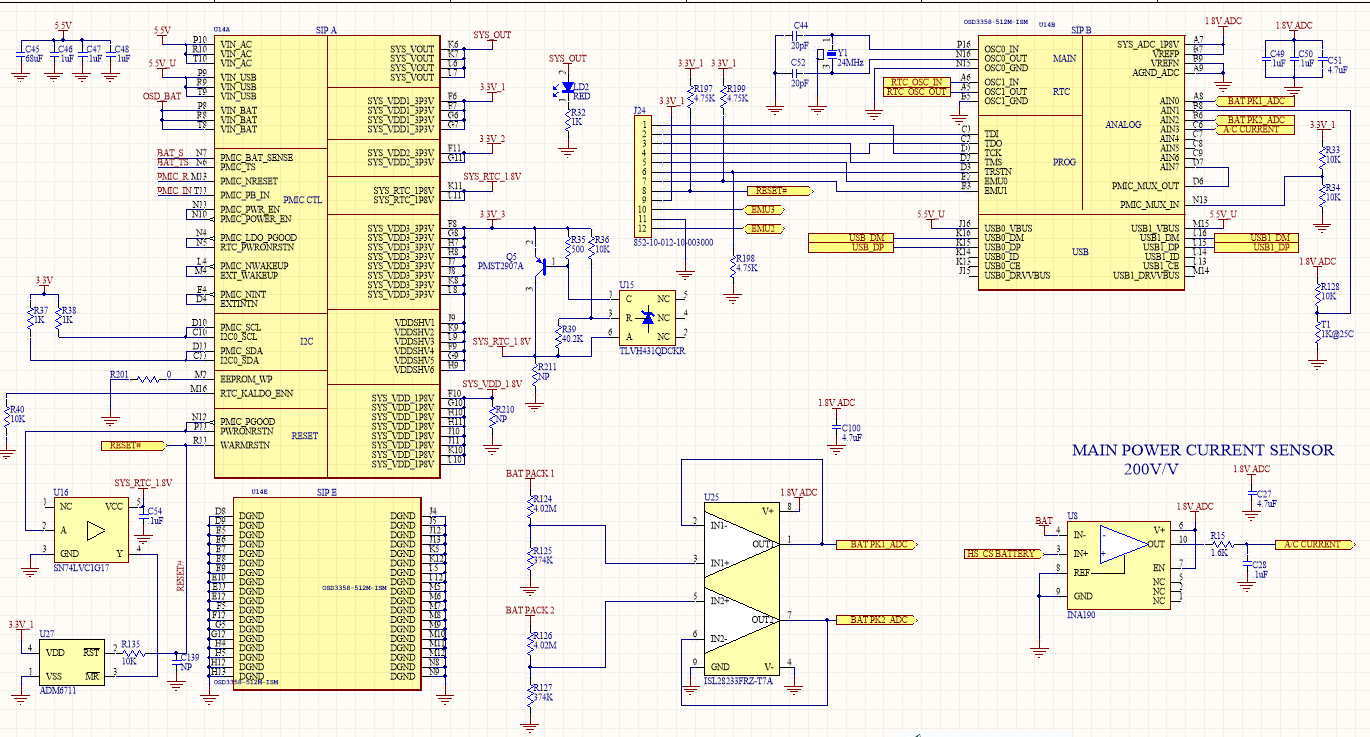
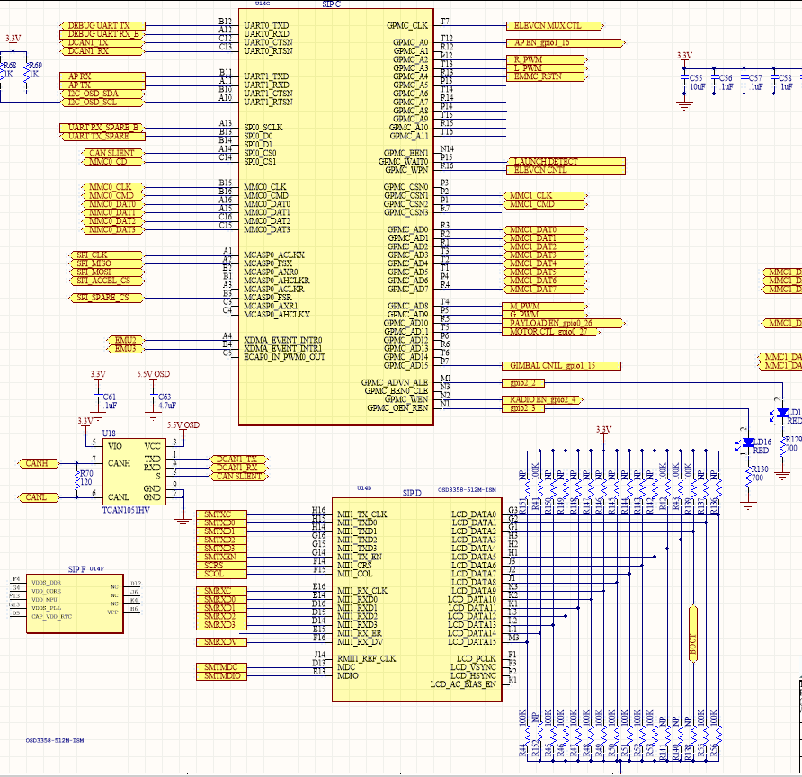
I have measured the 24MHz signal and it looks like it comes up about 1mS after the 3.3V_1 rail. I have also attached the schematic sheet associated with the boot pins.
Attachments:
- October 22, 2019 at 10:06 am #9274Neeraj DantuModerator
Mnagibulla,
This is interesting. The SYSBOOT configuration looks fine. Is there anything else on the LCD interface? The theory being the BOOT configuration is not being latched properly.
If that is not the case, we might have to take a closer look at your rev 2 and 3 schematics. Please contact our sales manager at martin.burgos(at)octavosystems.com.
Finally, are you seeing this issue on more than one board?
Neeraj
- October 22, 2019 at 4:28 pm #9277mnagibullaParticipant
3 out 4 boards have this problem. Only one doesn’t.
- February 7, 2022 at 2:23 pm #12046
 bpiquetteParticipant
Did you ever find a root cause for this issue?
- February 8, 2022 at 2:45 pm #12055Neeraj DantuModerator
We believe they were able to boot the board, but we do not have the root cause information on what the problem was.
Best,
Neeraj
- AuthorPosts
- You must be logged in to reply to this topic.
