STPMIC1 Non-Volatile Memory Programming Guide
Published On: June, 29, 2020 By: Justin Berry | Updated: December 1, 2020 by Cathleen Wicks
This application note describes how to reprogram the non-volatile memory (NVM) within the Power Management Integrated Circuit (PMIC), the STPMIC1, for OSD32MP15x Devices. The PMIC stores the initial configuration of the output power rails, startup conditions, etc. in NVM that is loaded during the power-up sequence. By default, the NVM in the OSD32MP15x is set to the values for the STPMIC1A configuration. However, a customer may want to modify this initial configuration in their application or design. For example, by default, the threshold voltage required to turn on the PMIC, VINOK_THRES, is 3.5 Volts. To power the OSD32MP15x using a 3.3 Volt regulator, the VINOK_THRES in NVM must be modified to a lower value. This application will walk you through an example of the 3 basic steps:
- preparing the software
- connecting the device
- reprogramming the NVM.

Table of Contents
1. Introduction STPMIC1 NVM
2. Setting Up the System
2.1. Hardware Setup
2.2. Software Setup
3. Reprogramming the PMIC
3.1. Prepare Scripts
3.2. Rewrite Values
4 Conclusion
5 Revision History
1 Introduction STPMIC1 NVM
The non-volatile memory (NVM) is described in detail in various sections within the STPMIC datasheet. Some important sections include:
- Section 6.7 – Description of all NVM registers
- Section 5.5.2 – General description of the NVM as well as detailed sections on the read and write operation of the NVM
For this application note, we have provided two Python scripts:
- pmic_read_reg.py – Will read PMIC registers specified within the script and print the values to the command line.
- pmic_reprogram_nvm.py – Will write the NVM registers with the values within the script and specified on the command line. By default, this script will re-write all NVM registers, but can easily be modified.
Both scripts run using Python version 3, i.e. python3, and are open source so that they can be easily customized for a given application. Details about script are in comments near the top and throughout the file.
Typically these scripts are run during the provisioning or test process in the manufacturing flow of the product, however they can be run at anytime if the NVM values need to be modified.
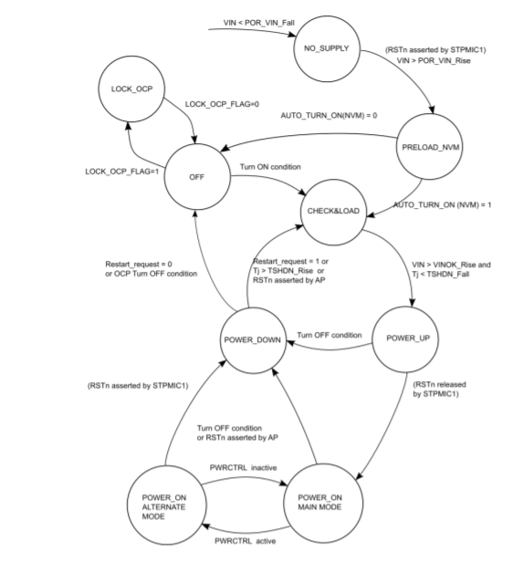
Below is a picture of the PMIC state machine. By making sure the device is adequately powered, you move from top to bottom along the right side of the state machine. Once the device is in POWER_ON/MAINMODE, you can reprogram the PMIC. Any new power up conditions will come into effect the next time the device is booted up.
In order for the NVM in the PMIC to be programmed the PMIC MUST BE IN THE POWER_ON/MAIN MODE state.
Since the PMIC needs to be fully powered on to be reprogrammed, the STM32MP15x processor inside the OSD32MP15x will also be powered and can be used to reprogram the NVM of the PMIC. The above scripts were designed to run on the STM32MP15x processor within the OSD32MP15x system-in-package device. However, they may be run on an external device connected to the I2C4 bus (i.e. the PZ4/PMIC_SCL and PZ5/PMIC_SDA pins) of the device.
2 Setting Up the System
This section will discuss the hardware and software required to set up and run the PMIC reprogramming software. In this application note, we will run the reprogramming scripts on the STM32MP1 processor inside the SiP, specifically we will use the OSD32MP1-BRK as our platform.
2.1 Hardware Setup
The hardware required to program the NVM in the PMIC is:
- A fully powered on OSD32MP15x SiP
- A device connected to the PMIC I2C lines (PZ4/PMIC_SCL, PZ5/PMIC_SDA) that can run the provided scripts.
In this example, no external components are needed to program the PMIC since the STM32MP15x processor is connected via I2C to the STPMIC1 within the OSD32MP15x.
If you choose to use an external device, you will need to make sure it is powered and connected to the PZ4/PMIC_SCL and PZ5/PMIC_SDA pins via I2C.
2.2 Software Setup
The software required for this application note is:
- An operating system with Python3 installed
- The scripts provided in Section 1.
No additional software components are needed.
Note: The Debian Linux image from Octavo Systems already contains the necessary python installation to run the provided software.
3 Reprogramming the PMIC
This section details the procedures to setup the OSDMP1-BRK and to reprogram the PMIC NVM.
3.1 Prepare the Scripts
The goal of this section is to get power to the device and make the necessary python scripts available for use on device. Each system is different so how you do this will depend greatly on your setup.
The following procedure describes the steps to load the Scripts on the OSD32MP1-BRK which was set up following the steps in the Getting Started Guide:
- Insert the microSD card with Debian Linux image into OSD32MP1-BRK
- Connect your OSD32MP1-BRK to your computer via the USB cable
- Use a terminal program, such as Putty or TeraTerm, to SSH into the OSD32MP1-BRK
- Using your preferred file transfer software, such as WinSCP, upload the provided software, i.e. the python files, to the SD card. In this example, these files were placed in the home directory of the default user “debian”, i.e. /home/debian.
3.2 Rewrite Values
The following procedure describes how to use the provided software to write new values to the PMIC NVM:
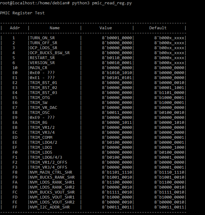
- Validate the connection to the STPMIC1 by reading the PMIC registers by running the pmic_read_reg.py script:
- Change to the root user. The software requires root permissions to execute correctly:
debian@localhost:~$ sudo su
			[sudo] password for debian:

			root@localhost:/home/debian#
- Run the script:
root@localhost:/home/debian# python3 pmic_read_reg.py
 The script is configured by default to run on the default Octavo Systems Debian Linux image for the OSD32MP1-BRK. In the default configuration the STPMIC1 is connected to the STM32MP15x on I2C4. Therefore, the script by default will use the I2C bus “3” (I2C buses are numbered 0,1,2, 3 in OS and alias I2C1, I2C2, I2C5, I2C4 ports) for communication. If your device tree configuration is different from the default Debian Image for the OSD32MP1-BRK board, you may need to check which I2C port the PMIC SCL and SDA, i.e. pin PZ4 and PZ5 on the SiP, are assigned. Below is an example error message if the I2C bus is not set properly.


To fix this, you can use the command argument “–-i2c=” to change the I2C bus number used to communicate to the PMIC. For example:root@localhost:/home/debian# python3 pmic_read_reg.py --i2c=”3”
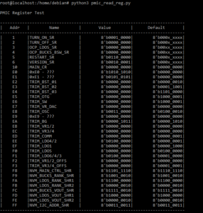

Successful Output If successful, the script will print out something like this:
- Change to the root user. The software requires root permissions to execute correctly:
- After validating the connection to the STPMIC1, you can now modify this PMIC NVM with the following command:
root@localhost:/home/debian# python3 pmic_reprogram_nvm.py
If you get the following error, your i2c bus number may be the problem:
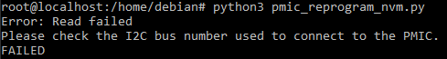

The i2c bus number should be the same as value from Step 1. To fix the error, you can use the command argument “–-i2c=” to change the I2C bus number used to communicate to the PMIC. For example:root@localhost:/home/debian# python3 pmic_reprogram_nvm.py --i2c=”3”
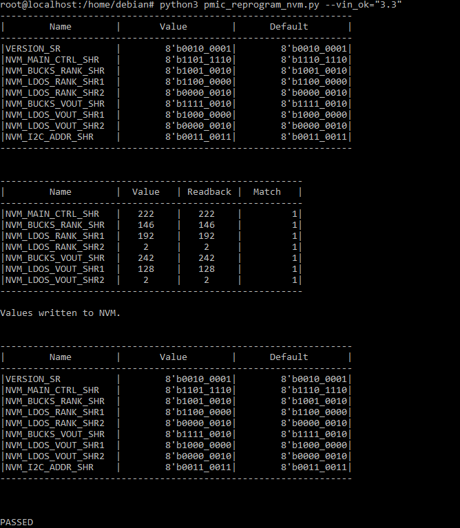
By default, the script sets VINOK_THRESH to 3.5V (i.e. the STPMIC1A configuration). If you wish to set it to another value, you can use the command argument “–vin_ok=” which can have a value of [“3.1”, “3.3”, “3.5”, or “4.0”} Volts. For example:
root@localhost:/home/debian# python3 pmic_reprogram_nvm.py --i2c=”3” --vin_ok=”3.3”
- When the value is written, you will see three tables and a message saying “PASSED”. For example:
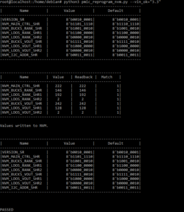

NVM Successful Written
With this, the NVM in the PMIC has been successfully reprogrammed.
4 Conclusion
This application note shows how to use the provided software to re-program the non-volatile memory (NVM) within the power management integrated circuit (PMIC) for the OSD32MP15x family of devices. For any questions or comments, please post on our forums.
5 Revision History
Get notified of updates to this Application Note and all of our Technical Documentation.
"*" indicates required fields
| Revision Number | Revision Date | Changes | Author |
|---|---|---|---|
| 1 | 6/26/2020 | Initial Release | Justin Berry |
