Powering the OSD335x, AM335x SiP, with LiPo and Li-Ion Batteries
Published On: July, 11, 2019 By: Eshtaartha Basu | Updated: June 30, 2020 by Neeraj Dantu
The TPS65217C Power Management Integrated Circuit (PMIC) within the OSD335x, the AM335x System in Package, Family of Devices provides a linear battery charger to support single-cell (1S) Lithium Ion (Li-Ion) and Lithium Polymer (LiPo) batteries. This gives a useful way to create AM335x battery applications. However, due to the voltage range of Li-Ion and LiPo batteries (approximately 3.0V to 4.2V) and the default settings of the PMIC, the TPS65271C is not able to support the full battery voltage range without software modifications. This application note will explore implementing AM335x battery applications by making the software changes necessary to support the full battery voltage range and provide updates to U-Boot to automatically modify the PMIC during boot.
Table of Contents
Abstract
1. Introduction to Implementing AM335x Battery Applications
2. UVLO and LDO Voltage Background
2.1 Battery Voltage < UVLO
2.2 Output Voltage of LDO2 or LDO4<3.1V
3. Register Configuration
3.1 U-Boot Patch
3.2 Linux Command Line
4. OSD335x Family Design Considerations
5. Reference Documents for Powering the OSD335x, AM335x for Battery Applications
6. Revision History of this Document
![]()
![]() A PDF version of this App Note can be found HERE
A PDF version of this App Note can be found HERE
![]()
![]() Download Software Associated with this App Note HERE
Download Software Associated with this App Note HERE

1 Introduction to Implementing AM335x Battery Applications
Within the OSD335x, resides the TPS65217C PMIC which easily supports AM335x battery applications The TPS65217C PMIC supports up to three input power sources: VIN_AC, VIN_USB and VIN_BAT. Typically, VIN_AC is used with a 5V AC Adapter; VIN_USB is used with a direct USB connection; and VIN_BAT is connected to a 1S Li-Ion or LiPo battery, see Figure 1. When using a battery, VIN_AC or VIN_USB can also be used to charge the battery, if necessary, while powering the system. When available, VIN_AC input has the highest priority for charging the battery and powering the system followed by VIN_USB. These priorities help reduce the usage of battery power whenever possible and extend its life by decreasing the number of charge and discharge cycles on the battery. The linear charger along with triple system power path of the PMIC allow for simultaneous and independent powering of the system and battery charging.
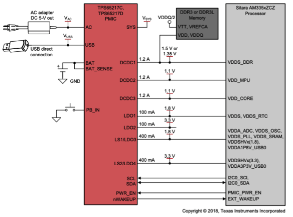
The TPS65217C features 3 DCDC converters and 4 LDOs which are used to power the AM335x processor within the OSD335x Family of devices as well as provide output current for the rest of the system, as shown in Figure 1. By default, LDO2 and LDO4 are configured to operate at 3.3V. This operating voltage combined with the Under Voltage Lock Out (UVLO) protection mechanism within the PMIC creates a minimum input voltage of approximately 3.4V. However, in considering AM335x battery applications, Li-Ion and LiPo batteries have an operating voltage range of 4.2V to 3.0V. Therefore, we can make modifications to the
- UVLO (Under Voltage Lock Out)
- Output voltages of LDO2, LDO4.
to utilize the full operating voltage range of the battery and extend the operating life of the system.
2 UVLO and LDO Voltage Background
Before we modify the Under Voltage Lock Out (UVLO) and LDO voltage settings, we need to understand some background information on what these settings are, why they need to be modified, and the registers used to make the modifications. This will help easily implement AM335x battery applications. There are many events and faults that can cause TPS65217C PMIC to shut off. These events/faults are described in detail under Power-Down Sequencing (8.3.1.2) section of TPS65217C datasheet. However, there are two faults that prevent operation below 3.3V.
2.1 Battery Voltage < UVLO
Many devices use Under Voltage Lock Out (UVLO) functionality to disable the device when the input voltage falls below a minimum voltage where the performance of the device can no longer be guaranteed. The TPS65217C provides 4 different UVLO voltage options since the power regulator output voltages are configurable. They are:
- 2.73V
- 2.89V
- 3.18V
- 3.3V (default on every reset)
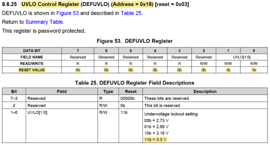
The UVLO voltage is defined in the DEFUVLO register of TPS65217C datasheet as shown in Figure 2. Given that we need the battery input to operate down to 3.0V, it is necessary to modify the DEFUVLO register to set it to 2.73V or 2.89V (i.e., DEFUVLO = 0x00, or DEFUVLO = 0x01).
In the example code provided, the UVLO is set to 2.73V. This should be done as early as possible in the boot process of the OSD335x device and is required on every power-up to avoid any power corner cases which could cause the PMIC to fault. The patch file provided (tps65217c_config.patch) will program the DEFUVLO register during U-Boot. More info about this patch and its usage is given in Section 3.1.
2.2 Output Voltage of LDO2 or LDO4 < 3.1V
The TPS65217C has two power-good logic signals that monitor the state of all the enabled output rails. The primary power-good signal, PGOOD monitors DCDC1, DCDC2, DCDC3, LDO3 and LDO4 power outputs. The secondary power-good signal, LDO_PGOOD, monitors LDO1 and LDO2. If a fault occurs on an enabled output rail such as a shorted output, Over Temperature Shutdown (OTS) condition, or UVLO condition, the corresponding PGOOD pin, the LDO_PGOOD pin, or both pins are pulled low, and all output rails are shut down.
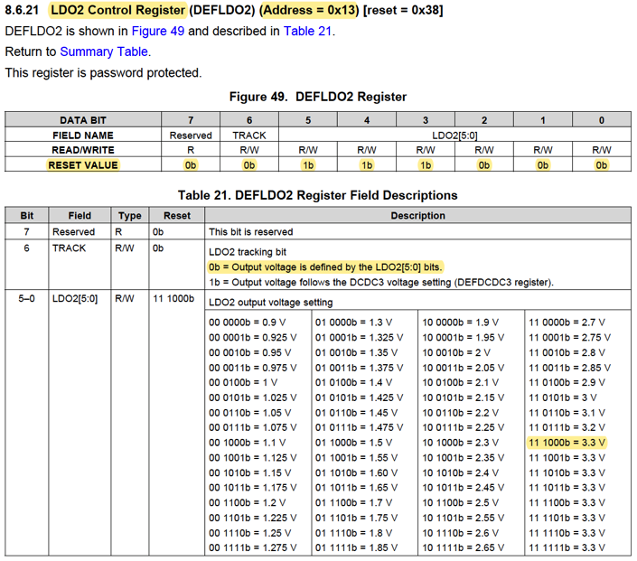
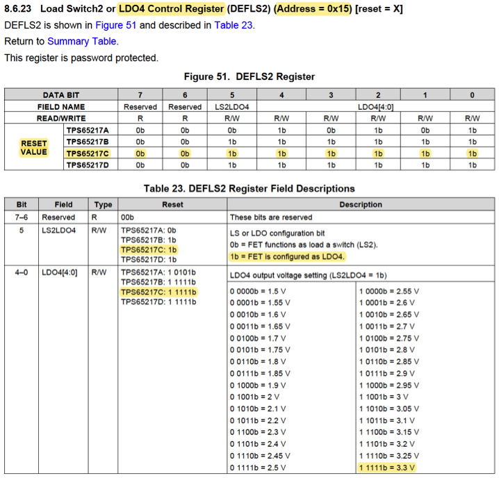
The output voltage of LDO2 and LDO4 default to 3.3V on every reset as defined in DEFLDO2, and DEFLS2 registers of TPS65217C datasheet (shown in Figure 3 and Figure 4). These LDOs have a dropout voltage of 0.2V, as defined by the datasheet. As a result, even if UVLO is set below 3.0V, the PGOOD and LDO_PGOOD will be pulled low and shut off the PMIC as soon as the input voltage falls below 3.1V (i.e. 3.3V minus the 0.2V dropout). Therefore, to support an input voltage below 3.3V, it is necessary to modify the output voltages of LDO2 and LDO4.
In the example code provided, LDO2 and LDO4 are set to 2.8V. This should be done as early as possible in the boot process of the OSD335x device and is required on every power-up to avoid any power corner cases which could cause the PMIC to fault. The patch file provided (tps65217c_config.patch) will program the DEFLDO2 and DEFLS2 registers during U-Boot. More info about this patch and its usage is given in Section 3.1.
3 Register Configuration
The PMIC registers in the OSD335x Family of devices can be configured over the I2C0 bus. This configuration can be done at many points during the boot process, such as the Secondary Program Loader (SPL), U-Boot, Linux boot, or from the Linux command line after boot. This application note will detail how to configure the PMIC registers during U-Boot through the use of a U-Boot patch as well as the commands required to be used on the Linux command line after boot.
3.1 U-Boot Patch
U-Boot is a standard, open-source bootloader that is executed by the AM335x processor after the ROM bootloader and SPL. Its purpose is to configure the system such that Linux can begin execution. Since it is open-source, it is straightforward to modify to provide additional functionality. Additionally, it is executed early in the boot process so that the PMIC registers can be configured quickly to prevent power corner cases.
A U-Boot patch, tps65217c_config.patch, has been provided to automatically set UVLO = 2.73V and LDO2 = LDO4 = 2.8V in U-Boot. You can download this patch here This patch needs to be applied to U-Boot source code before building it. The steps to apply U-Boot patch are as follows:
- Download, install and test the GCC Cross Compiler on an Ubuntu Host PC using steps given under ARM Cross Compiler: GCC section of https://www.digikey.com/eewiki/display/linuxonarm/BeagleBone+Black
- Download U-Boot and apply 0001-am335x_evm-uEnv.txt-bootz-n-fixes.patch, 0002-U-Boot-BeagleBone-Cape-Manager.patch using steps given under Bootloader: U-Boot section of https://www.digikey.com/eewiki/display/linuxonarm/BeagleBone+Black
- Once the above two patches are applied, apply patch
- Configure and build U-boot using the last step given under Bootloader: U-Boot section of https://www.digikey.com/eewiki/display/linuxonarm/BeagleBone+Black. Once U-Boot build process completes, you will be able to see two files in U-Boot source directory: MLO and u-boot.img
- Flash a microSD card with RED Debian image or one of the BeagleBoard images and insert it to Host PC using a microSD card reader.
- Find the partition ID of your microSD card using lsblk command on command line of Host PC.
- Copy U-boot files to microSD card using the following commands:
1 2 3 | export DISK=/dev/<uSD device partition number> sudo dd if=./<U-Boot source directory>/MLO of=${DISK} count=1 seek=1 bs=128k conv=fdatasync sudo dd if=./<U-Boot source directory>/u-boot.img of=${DISK} count=2 seek=1 bs=384k conv=fdatasync |
- Eject the microSD card from the host PC and insert it into your OSD335x based design. (You can alternately use other methods to program the non-volatile storage on your design with the updated image, such as https://octavosystems.com/app_notes/programming-emmc-with-usb/)
- When you boot the board you can observe messages about the PMIC registers being programmed on the UART0 serial console as shown in Figure 5.
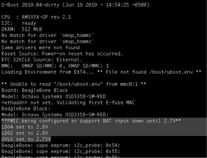

Figure 5 PMIC Configuration boot messages
3.2 Linux Command Line
To prototype or experiment with the PMIC settings, it is possible to configure registers using the i2c commands on the Linux command line. The PMIC registers require a “password” in order to be modified. You can find the commands that need to be executed to set UVLO = 2.73V and LDO2 = LDO4 = 2.8V below:
1 2 3 4 5 6 7 8 9 10 11 12 13 14 15 | i2cset -f -y 0 0x24 0x0B 0x65 # write 0x18 XORed with 0x7D to password reg. i2cset -f -y 0 0x24 0x18 0x00 # set DEFUVLO register to 2.73V i2cget -f -y 0 0x24 0x18 # read DEFUVLO reg. (Expected value = 0x00) i2cset -f -y 0 0x24 0x0B 0x6E # write 0x13 XORed with 0x7D to password reg. i2cset -f -y 0 0x24 0x13 0x32 # set DEFLDO2 register to 2.8V i2cset -f -y 0 0x24 0x0B 0x6E # repeat above 2 steps (Level 2 protection) i2cset -f -y 0 0x24 0x13 0x32 i2cget -f -y 0 0x24 0x13 # read DEFLDO2 reg. (Expected value = 0x32) i2cset -f -y 0 0x24 0x0B 0x68 # write 0x15 XORed with 0x7D to password reg. i2cset -f -y 0 0x24 0x15 0x35 # set DEFLS2 register to 2.8V i2cset -f -y 0 0x24 0x0B 0x68 # repeat above 2 steps (Level 2 protection) i2cset -f -y 0 0x24 0x15 0x35 i2cget -f -y 0 0x24 0x15 # read DEFLS2 reg. (Expected value = 0x35) |
4 OSD335x Family Design Considerations
While designing an OSD335x based system for AM335x battery applications with < 3.3V operation on VIN_BAT, please keep the following considerations in mind:
- Since the LDO2 (SYS_VDD2_3P3V) and LDO4 (SYS_VDD3_3P3V) outputs will be below 3.3V, all the components being powered using those output power rails need to be able to operate below 3.3V as described in the caveat of Section 0.
- The SYS_VOUT power output voltage follows the power input voltage minus a small dropout voltage (approximately 100mV depending on the power input). Therefore, when running on a battery input, SYS_VOUT will be slightly less than the battery voltage and well below 5V. This means that it is no longer a suitable power rail to use to power USB devices. Additionally, any device using SYS_VOUT has to be able to support operation up to 5V. When the VIN_AC or VIN_USB power inputs are used to charge the battery, SYS_VOUT will be approximately 5V.
- At the time of power-up, the battery voltage on the VIN_BAT pin should be at least ~3.7V as described in the Caveat of Section 3.2.
5 Reference Documents for Powering the OSD335x, AM335x for Battery Applications
- TPS65217C datasheet
- AM335x datasheet
- Powering the AM335x with TPS65217C
- AM335x power consumption summary
- AM335x Power Management User Guide
6 Revision History
| Revision Number | Revision Date | Changes | Author |
|---|---|---|---|
| 1 | 7/11/2019 | Initial Release | E. Basu |
