Programming eMMC with USB for OSD335x (AM335x System in Package)
Published On: February, 15, 2019 By: Neeraj Dantu | Updated: January 31, 2020 by Neeraj Dantu
One of the key steps in producing an embedded design is to program the device with production software or firmware. For a microprocessor-based design, the production software generally consists of a custom Linux image which is programmed into the non-volatile memory on the design. Because the size of a Linux image can be a few gigabytes and the interface of the non-volatile memory may only be connected to the processor, programming this image can be costly and time consuming when scaling for a large quantity of devices. This app note describes a procedure for programming eMMC with USB for OSD335x (AM335x System in Package) via a USB client interface.
The procedure described in this app note requires only a single USB cable to both power the embedded design and transfer all the necessary information. However, this procedure does not require that the embedded design be powered off of the USB cable and can be easily modified to support different power designs. A host computer is required to serve the custom Linux image which will be programmed on to the devices. This solution can scale because one host computer can be used to program many devices in parallel with minimal human interaction, allowing production quantities of devices to be programmed in a cost effective and timely manner. Scaling does have hardware limitations such as the processor and the USB data speeds of the host computer, which can be chosen based on target program time.
The procedure for programming eMMC with USB for OSD335x (AM335x System in Package) described in this document assumes that the OSD335x embedded design has a USB client port connected to USB0 and an eMMC memory connected to MMC1. Additionally, the host computer is assumed to be running Ubuntu 16.04.
Table of Contents
1.Introduction
2.Procedure Overview
2.1.Terminology
3.Requirements for Procedure
4.Initial Setup
4.1Setup TFTP Server on Host Computer
4.2Setup DHCP Server on Host Computer
4.3Boot Components for “Target Device”
4.3.1Pre-Built Boot Components
4.3.2Customizing Boot Components
4.4Automated “Target Device” Programming on “Host Computer”
4.4.1Detect USB Storage Gadget
4.4.2Copy Production Software Image to “Target Device
5.Programming Setup Overview
6.Programming “Target Devices”
7.Helpful Debugging Tips
8.Revision History
![]()
![]() A PDF version of this App Note can be found here.
A PDF version of this App Note can be found here.
![]()
![]() Files associated with this App Note can be downloaded here.
Files associated with this App Note can be downloaded here.

2 Procedure Overview
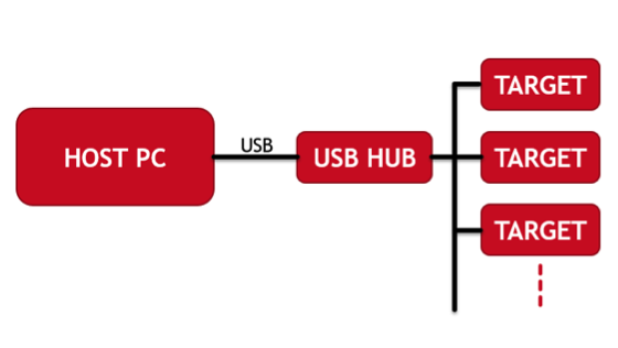
Figure 1 shows an example hardware setup for the procedure for shows an example hardware setup for the procedure of programming eMMC with USB for OSD335x (AM335x System in Package). The “OSD335x Target Device” is connected to the “Host Computer” via USB. Optionally, the USB connection can utilize a “USB Hub” so that multiple devices may be programmed at the same time. The USB port on the “Target Device” is a USB client port and will be used as the boot interface of the device. The USB port on the “Host Computer” is a USB host port and will be used to transfer the information to the device.
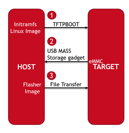
The programming procedure has two major steps: 1) A small, light-weight, initramfs (Initial RAM Filesystem) based Linux image is booted on the “OSD335x Target Device” using TFTP over the USB interface 2)The minimal image booted on the target will provide the “Host Computer” access to the attached eMMC memory as a mounted mass storage device, similar to a USB flash drive; 3) The “Host Computer” will copy the production Linux image to the eMMC memory.
2.1 Terminology
Before continuing, please familiarize yourself with the Linux Boot Process on the OSD335x Family of Devices. The following sections will refer to different components of the boot process described in this article.
Additionally, understanding networking concepts such as:
while not necessary, can provide additional context for the steps described in the procedure.
3 Requirements for Procedure
These are the basic requirements for implementation of the procedure described in this document:
- Host Computer. Current tested platforms include:
- Ubuntu (16.04 LTS)
- OSD335x Target Device with
- USB client port attached to USB0
- eMMC memory attached to MMC1
- Boot Mode setting (i.e. SYSBOOT[4:0] value) that includes USB0 as a boot device (e.g. SYSBOOT[4:0] = 11000b has boot peripherals of SPI0, MMC0, USB0 and UART0)
- Optional LED indicators to be set at different points of the flashing process to act as feedback
- Optional USB Hub
The boot components can be modified to support different hardware configurations of the “Target Device”. See Section 5.3.2 for more details.
4 Initial Setup
The example hardware setup was shown in Figure 1. This procedure assumes that the production Linux image (.img) has already been prepared and has been stored on the “Host Computer”. The initial software setup consists of the following steps:
- Setup a TFTP server on “Host Computer”
- Setup a dummy ethernet connection to assign IP address to ethernet interface of “Host Computer” when a “Target Device” is connected
- Setup a DHCP server on “Host Computer”
- Download or create the boot components necessary to bootstrap the “Target Device”
- Setup automatic scripts on the “Host Computer” to boot and program eMMC on “Target Device”
4.1 Setup TFTP Server on Host Computer
The TFTP server is used to serve the boot components for the “Target Device”. The following steps describe the process of installing and setting up a TFTP server on an Ubuntu (16.04 LTS) computer:
- Install required packages:1$sudo apt-get install xinetd tftpd tftp
- Edit configuration file for the TFTP server in file /etc/xinetd.d/tftp. If the file is not present, it needs to be created. Modifying this file also requires root privileges. Note that the “server_args” variable refers to the folder where files that need to be served are located.1234567891011service tftp{protocol = udpport = 69socket_type = dgramwait = yesuser = nobodyserver = /usr/sbin/in.tftpdserver_args = /tftpbootdisable = no}
- Create the folder referenced by variable “server_args” and set appropriate permissions:123$sudo mkdir /tftpboot$sudo chmod -R 777 /tftpboot$sudo chown -R nobody /tftpboot
- Restart xinetd service to run the TFTP server:1$sudo service xinetd restart
- To verify whether the service is running properly:1$sudo systemctl status xinetd
4.2 Setup DHCP Server on Host Computer
To communicate over TFTP, the “Host Computer” and the “Target Device” need to be on the same IP subnet. This is accomplished by running a DHCP server on the “Host Computer”. When the “Target Device” tries to boot, it will send BOOTP requests over the USB RNDIS interface. The DHCP server running on the “Host Computer” will then assign the “Target Device” an IP address. This will then allow the “Target Device” to request the necessary boot components from the TFTP server. The procedure to setup a DHCP server is described in the following steps:
- Install required packages1$sudo apt-get install isc-dhcp-server
- Edit the DHCP server parameters in existing /etc/dhcp/dhcpd.conf dhcp configuration file or create a new one.Note that the configuration file sets up the “Host Computer” (i.e. the DHCP server) at 192.168.0.1 and will assign IP addresses between 192.168.0.2 and 192.168.0.100. These parameters are arbitrary and can be changed if needed. The configuration file also sets the files to be transferred for different BOOTP requests using vendor class identifiers. These file names will be used to name the boot components that will be defined later in this document.123456789101112131415161718192021222324252627ddns-update-style none;ignore-client-uids on;default-lease-time 600;max-lease-time 7200;log-facility local7;option domain-name "tftpboot";subnet 192.168.0.0 netmask 255.255.255.0{range dynamic-bootp 192.168.0.2 192.168.0.100;if substring (option vendor-class-identifier, 0, 10) = "AM335x ROM"{filename "u-boot-spl-restore.bin";}elsif substring (option vendor-class-identifier, 0, 10) = "DM814x ROM"{filename "u-boot-spl-restore.bin";}elsif substring (option vendor-class-identifier, 0, 17) = "AM335x U-Boot SPL"{filename "u-boot-restore.img";}else{filename " u-boot-spl-restore.bin ";}range 192.168.0.101 192.168.0.199;}
- Configure the DHCP server to automatically run on the dynamically created USB RNDIS network interfaces which needs to have the IP address of the server (192.168.0.1) through an interface startup script:
- Create /etc/network/if-up.d/dhcp-restartFirst, the script checks whether the name of the interface matches with any known interfaces. The example “Host Computer” had two network interfaces: eno1 (i.e. wired Ethernet port) and lo (Loopback). If your “Host Computer” has different or additional network interfaces, the if statement(line 8) needs to be modified appropriately so that nothing will occur for those interfaces. If the name does not match, the script then sets the IP address of the “Host Computer” on the new interface. Then it checks whether the interface is already configured for the DHCP server using the /etc/default/isc-dhcp-server configuration file. If the interface is not present, the script adds the name of the new interface to the INTERFACES variable in the file. Finally, it restarts the DHCP server with the new configuration.1234567891011121314151617181920#!/bin/sh## Modify the /etc/default/isc-dhcp-server init script to include the new RNDIS network# interfaces in dhcp server configuration. It will then restart the dhcp server# Static network interfaces that should not be modified# *** Add any other static network interfaces on your host computer ***if [ "$IFACE" = "eno1" ] || [ "$IFACE" = "lo" ]; then:elseifconfig $IFACE 192.168.0.1 netmask 255.255.255.0if grep -q "$IFACE" /etc/default/isc-dhcp-serverthen:elsesed -i "/INTERFACES/ s#"$# $IFACE"#g" /etc/default/isc-dhcp-serverfi;fi;systemctl restart isc-dhcp-server
- Modify the permissions of the file to make it executable1$sudo chmod +x /etc/network/if-up.d/dhcp-restart
- Create /etc/network/if-up.d/dhcp-restart
- Create a dummy ethernet connection to set an IP address to the network interface of the “Host Computer” the “Target Device” is connected to. This will complete the initial setup of the ethernet connection and will allow to execute the “dhcp-restart” script created in step 3.
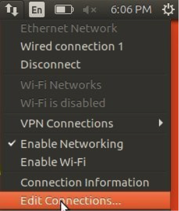
- Select the Ethernet Connections menu on the desktop and select on ‘edit connections’

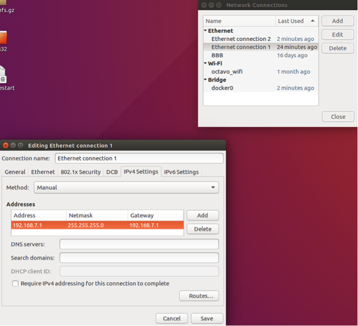
- Select “Add” in the Network Connections window. Edit the new Network Connection configuration: Select “IPv4 Settings” tab and enter any valid, IP address, netmask and gateway.

- Select the Ethernet Connections menu on the desktop and select on ‘edit connections’
Restarting the DHCP server during the TFPT activity required to boot the “Target Device” can result in an incomplete boot. Therefore, each additional “Target Device” to be programmed should not be connected to the “Host Computer” until the previous “Target Device” has completed booting. This state can be indicated by an LED as described in section 5.4.2.
4.3 Boot Components for “Target Device”
Now that the TFTP and DHCP server are configured on the “Host Computer”, the “Target Device” can download the necessary boot components from the “Host Computer”. These components available in the project download folder must be copied to the tftpboot folder set by variable server_args in file /etc/xinetd.d/tftp. There are five (5) boot components needed (Note: component names match names used in previous sections):
- u-boot-spl-restore.bin: Second stage bootloader (SPL) requested by ROM code. Performs device initialization including DDR setup.
- u-boot-restore.img: U-Boot bootloader requested by the SPL. Loads the Linux kernel, file system and device tree into memory.
- uImage: Linux kernel image with a U-Boot header describing the image. This kernel needs to be built to support a RAM based filesystem and have the necessary USB gadget drivers to expose the eMMC device via USB as a mass storage device.
- initramfs: Small filesystem built from Busybox that can live entirely within the DDR memory. This file is an archived zipped version of the filesystem generated by the busybox utility with minor modifications and a U-Boot header.
- osd3358-bsm-refdesing.dtb: Device Tree Binary (dtb) describing the hardware configuration of the “Target Device”. This file is responsible for setting up the eMMC and the USB interfaces.
4.3.1 Pre-Built Boot Components
You can find pre-built versions of the boot components here: Project Download Folder. The folder should contain the file mentioned above. The pre-built components can be used if the “Target Device” has:
- USB0 configured as a client port
- eMMC memory attached to MMC1
- Boot Mode setting (i.e. SYSBOOT[4:0] value) that includes USB0 as a boot device
If the target board does not satisfy the above conditions, some modifications are required for the bootloader and the filesystem.
4.3.2 Customizing Boot Components
If the embedded design cannot use the pre-built boot components, then custom boot components will need to be created. The source files of the bootloader and the RAM filesystem can be found here: Project Download Folder.. To modify the boot components, both the bootloader and the filesystem will need to be created.
4.3.2.1 Customizing U-Boot bootloader
There can be several reasons to modify the bootloader such as modifying boot arguments, booting from a different boot interface such at the ethernet or the UART. Configuration changes can be made via menuconfig. The U-Boot bootloader source files can be downloaded from here: Project Download Folder.
The following steps describe the how to modify configuration and build u-boot binaries (these steps are based those found at: https://www.digikey.com/eewiki/display/linuxonarm/BeagleBone+Black):
- Download and extract cross compiler (each command separated by ‘$’)123$wget -c https://releases.linaro.org/components/toolchain/binaries/6.4-2018.05/arm-linux-gnueabihf/gcc-linaro-6.4.1-2018.05-x86_64_arm-linux-gnueabihf.tar.xz$tar xf gcc-linaro-6.4.1-2018.05-x86_64_arm-linux-gnueabihf.tar.xz$export CC=`pwd`/gcc-linaro-6.4.1-2018.05-x86_64_arm-linux-gnueabihf/bin/arm-linux-gnueabihf-
- Verify cross compiler1234${CC}gcc --versionarm-linux-gnueabihf-gcc (Linaro GCC 6.4-2018.05) 6.4.1 20180425 [linaro-6.4-2018.05 revision 7b15d0869c096fe39603ad63dc19ab7cf035eb70]Copyright (C) 2017 Free Software Foundation, Inc.This is free software; see the source for copying conditions. There is NO warranty; not even for MERCHANTABILITY or FITNESS FOR A PARTICULAR PURPOSE.
- Extract and change directory to U-Boot source(May require package libncurses. Command included to install it)1234$ sudo apt-get install libncurses-dev$tar -xzf u-boot-tftp.tar.gz$cd u-boot-tftp$make ARCH=arm CROSS_COMPILE=${CC} menuconfig
- Edit configuration using menuconfig:
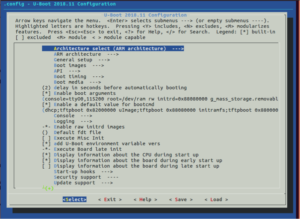

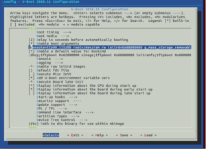
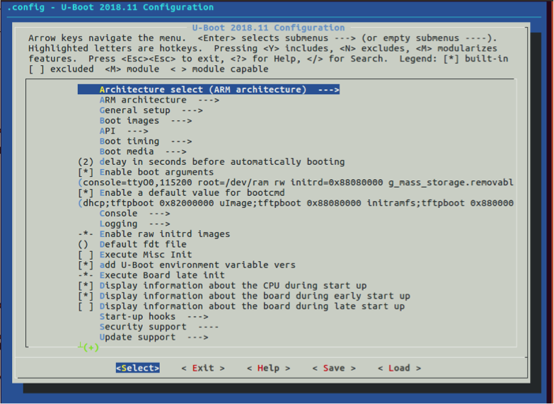
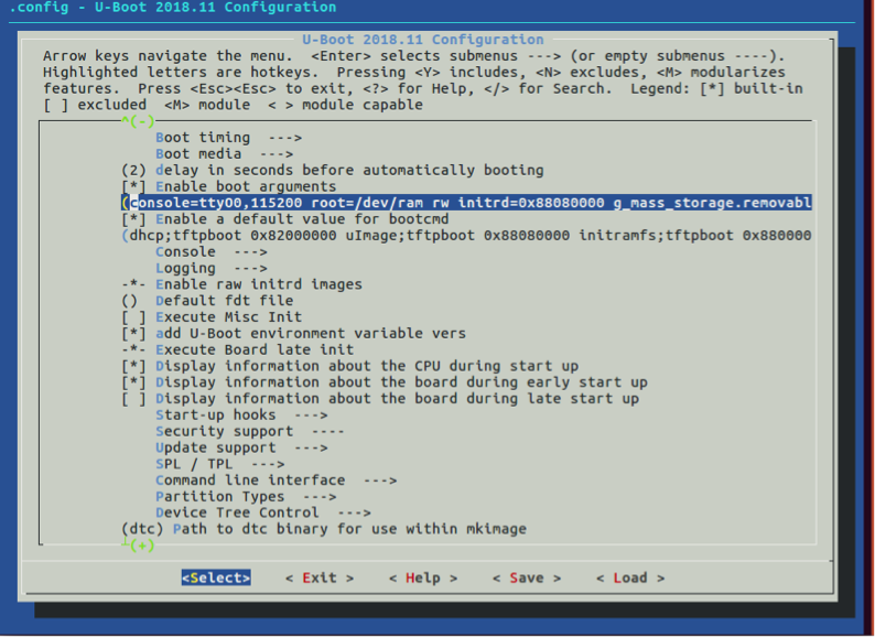
- To change the boot arguments, edit the “Enable boot arguments” field(Default: console=ttyO0,115200 root=/dev/ram rw initrd=0x88080000 g_mass_storage.removable=1 g_mass_storage.luns=1):

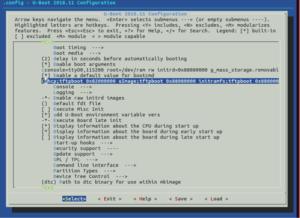
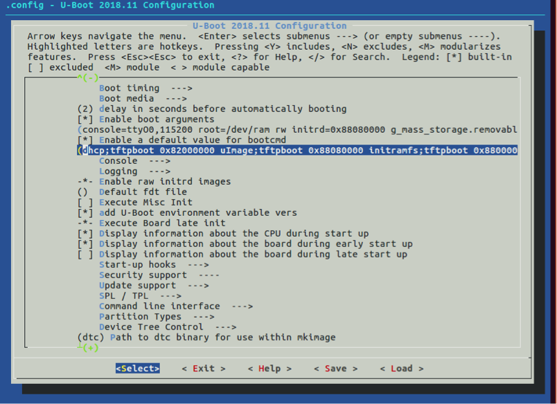
- To change the boot command, edit the “Enable a default value for bootcmd” field(Default: dhcp;tftpboot 0x82000000 uImage;tftpboot 0x88080000 initramfs;tftpboot 0x88000000 osd3358-bsm-refdesign.dtb;gpio set 54;bootm 0x82000000 0x88080000 0x88000000):

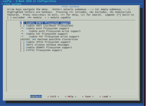
- To add support for another filesystem, select the appropriate option(s) in “Filesystems”:

- Additional modifications of tasks u-boot needs to perform such as turning on an LED to indicate the target has acquired and is running u-boot through TFTP are described in 5.3.2.3
- When finished modifying the configuration, save and exit menuconfig
- Build U-Boot1$make ARCH=arm CROSS_COMPILE=${CC}
- Copy the SPL and U-Boot to the TFTP server folder specified in the TFTP server configuration (e.g. /tftpboot/)Cd12$cp spl/u-boot-spl.bin /tftpboot/u-boot-spl-restore.bin$cp u-boot.img /tftpboot/u-boot-restore.img

4.3.2.2 Customizing Filesystem
The filesystem is where changes to initialization scripts and board setup for programming can be made. For example, the eMMC attached to the OSD335x can be on an MMC interface other than MMC1, which can be changed by updating the “init” script. The Busybox filesystem source files can be downloaded from here: Project Download Folder.
The following steps describe how to modify and build a filesystem:
- Extract file system and change directory to the filesystem12$tar -xzf RFS_static.tar.gz$cd RFS_static/
- Edit the file init file in the root directory of the new filesystem. For example, to change the eMMC interface change the ‘/dev/mmcblk1’ to the appropriate /dev/ input. The trailing number of the dev input corresponds to the MMC interface the storage device is connected to. Additional shell commands can be added to perform functions such as programming a board identification into an EEPROM and turning on an LED to indicate Linux kernel has booted(described in section 5.3.2.3).1234567891011121314151617#!/bin/sh/bin/mount -t proc none /proc/bin/mount -t sysfs sysfs /sysmdev -secho /dev/mmcblk1 > /sys/devices/platform/ocp/47400000.usb/47401400.usb/musb-hdrc.0/gadget/lun0/filecat <<'EOF'___ ____ ___ _______________ _____ _ _/ _ / ___|| _ ___ /___ / ___|_ __ | ___| | __ _ ___| |__ ___ _ __| | | ___ | | | ||_ |_ ___ / /| |_ | |/ _` / __| '_ / _ '__|| |_| |___) | |_| |__) |__) |__)> < | _| | | (_| __ | | | __/ |___/|____/|____/____/____/___/_/_|_| |_|__,_|___/_| |_|___|_|EOF/bin/sh
- Add the filesystem to a cpio archive (Command assumes current directory is */RFS_static/)1$find . | cpio -H newc -o > ../initramfs.cpio
- Change directory to the parent directory and zip the cpio archive12$cd ..$cat initramfs.cpio | gzip > initramfs.gz
- Add the U-Boot header to make the filesystem binary U-Boot compatible(May require package u-boot-tools. Command included to install it)12$ sudo apt install u-boot-tools$mkimage -A arm -O Linux -T ramdisk -C none -a 0x80800000 -n "RootFilesystem" -d initramfs.gz initramfs
- Copy the initramfs to TFTP folder specified in the TFTP setup. For example, /tftpboot/1$cp initramfs /tftpboot/
4.3.2.3 LED indicators
Since the boot and programming processes can be opaque to an operator, it can be useful to communicate progress using LEDs or other visual indicators on the “Target Device”. In the OSD335x reference designs, there are a number of “User LEDs” that can be used for this purpose. When communicating to an operator, there are two main points in the flashing process that should be indicated:
- When the “Target Device” has completed booting and is ready to have data transferred from the “Host Computer” to the eMMC.
Given that there are multiple boot components and multiple TFTP file transfers, it is important to indicate when the “Target Device” has completed booting. This indicates to the operator that it is safe to connect a new “Target Device” to the “Host Computer” to pipeline the programming process (DHCP server must not be restarted during the “Target Device” boot process). To do this, insert the appropriate commands when modifying “Enable a default value for bootcmd” during the U-Boot customization process described in Section 5.3.2.1. For example, the pre-built boot components set GPIO54, which is attached to a user LED, to ‘1’ after all of the TFTP file transfers of boot com0ponents have completed but before the kernel has booted. This can be found as part of the ‘bootcmd’ here:
1 | dhcp;tftpboot 0x82000000 uImage;tftpboot 0x88080000 initramfs;tftpboot 0x88000000 osd3358-bsm-refdesign.dtb;gpio set 54;bootm 0x82000000 0x88080000 0x88000000 |
- When the “Target Device” has completed programming the eMMC with data from the “Host Computer”.
When the “Target Device” has completed programming the eMMC, the “Target Device” is ready to be disconnected from the “Host Computer” and is ready for further verification and validation. There are multiple ways to indicate that the eMMC has finished being flashed. In the pre-built boot components, this is implemented by specifying an LED in the device tree to indicate eMMC activity. When the eMMC is being programmed, the LED will flash indicating activity on MMC interface. When the flashing is complete, the LED stops flashing and remains turned off. The snippet below shows part of the device tree used to configure pin 22 or GPIO bank 1 as the GPIO indicating MMC interface activity.
1 2 3 4 5 6 | led3 { label = "beaglebone:green:usr1"; gpios = <&gpio1 22 GPIO_ACTIVE_HIGH>; linux,default-trigger = "mmc0"; default-state = "off"; }; |
4.4 Automated “Target Device” Programming on “Host Computer”
In order to automate the “Target Device” programming, the “Host Computer” must:
- Detect the USB storage gadget presented by the “Target Device” once it has booted
- Copy the production software image to the “Target Device” via the USB storage gadget
The following subsections describe how each of these steps can be achieved. There are a number of files that need to created and or modified for this purpose available in the flasher subfolder of project download folder. The files and their assumed default locations are described below:
- /home/lab/flasher/list_gen.sh
- Script to be run by udev when USB storage gadget is detected
- /home/lab/flasher/list.txt
- List of current USB storage gadget devices; generated by sh
- /home/lab/flasher/usb_flasher.py
- Script to be run on “Host Computer” to monitor list of USB storage gadget devices and copy production software image to “Target Device”
- /home/lab/flasher/bone-debian-9.3-iot-armhf-2018-03-05-4gb.img
- Production software image to be copied to “Target Device”
These are arbitrary and can be modified to better match the filesystem of the “Host Computer”
4.4.1 Detect USB Storage Gadget
Once the “Target Device” has booted, it will expose the eMMC via a USB storage gadget to the “Host Computer”. By default, the “Host Computer” operating system will automatically detect when a new USB storage gadget is connected, similar to how the operating system automatically detects when a USB flash drive is inserted into a USB port. To perform an action when the USB storage gadget is detected, a udev rule can be added to the “Host Computer”.
- Create a script (e.g. list_gen.sh) to record the device names (e.g. /dev/sdb) when USB storage gadget is detected by “Host Computer” operating system
- Edit the script and add the following contents:Note that list.txt needs to be created and its path assigned to the OUTPUT variable in list_gen.sh script. Only device names that end in a character and not a number are added to the list of devices to be programmed (i.e. /home/lab/flasher/list.txt). This is because the udev rule will be triggered two times for each Linux file storage gadget detection. Once when the storage gadget is detected and the other when the storage gadget is mounted. For example, if the file storage gadget is attached to the “Host Computer” as /dev/sdb, the device /dev/sdb1 is also created to mount the storage gadget. Therefore, the script filters out the ‘sdb1’ interface and does not add it to the list of devices to be programmed to avoid duplicate copies of the same device.123456789#!/bin/bash# This script modifies and appends the device name to the list of devices to be programmed.OUTPUT="/home/lab/flasher/list.txt"if [[ $1 != *[0-9] ]]thenecho $1 >> $OUTPUTfi
- Make list_gen.sh executable1$Sudo chmod +x list_gen.sh
- Create /etc/udev/rules.d/98-osd335x-usb-flasher.rules1$Sudo nano /etc/udev/rules.d/98-osd335x-usb-flasher.rules
- Edit the new file and add the following contents replacing the filename /home/lab/flasher/list_gen.sh with the name and absolute path of the script created in step 1. The interface file name (e.g. /dev/sdX) is passed to the script as the input ‘%k’.:123# /etc/udev/rules.d/98-osd335x-usb-flasher.rulesACTION=="add", SUBSYSTEM=="block", SUBSYSTEMS=="scsi", ATTRS{model}=="File-Stor Gadget", ATTRS{vendor}=="Linux ", RUN:="/home/lab/flasher/list_gen.sh %k"
4.4.2 Copy Production Software Image to “Target Device”
By using the udev rule and associated script to create a list of devices to be programmed, it makes it easy for a script to monitor the list for changes and create a new thread to copy the production software image to the “Target Device”. The monitor script (e.g. /home/lab/flasher/usb_flasher.py) is described below and can be modified based on the needs of the “Target Device”. Specifically, base_path, list_path and img_file variables need to be assigned to the proper file paths similar to the paths shown below. The monitor script uses the Linux command dd to copy the production software image to the “Target Device”. This script will be run on the “Host Computer” continuously while a “Target Device” needs to be programmed. The contents of the script are:
1 2 3 4 5 6 7 8 9 10 11 12 13 14 15 16 17 18 19 20 21 22 23 24 25 26 27 28 29 30 31 32 33 34 35 36 37 38 39 40 41 42 43 44 45 46 47 48 49 50 51 52 53 54 55 56 57 58 59 60 61 62 63 64 | #!/usr/bin/python3 # This script will monitor list.txt and copy production software image. import time import subprocess import os import threading from watchdog.observers import Observer from watchdog.events import FileSystemEventHandler base_path = "/home/lab/flasher" list_path = "/home/lab/flasher/list.txt" img_file = "/home/lab/flasher/bone-debian-9.3-iot-armhf-2018-03-05-4gb.img" TIMEOUT = 1200 running_threads = [] def ddcopy(last_line): """ Funtion that will copy img_file to device """ os.system('sudo dd if=' + img_file + ' of=/dev/' + last_line.rstrip()) def clean_up_threads(): """ Clean up any threads that exceed the timeout value or have completed execution """ for thread in running_threads: if not thread.is_alive(): running_threads.remove(thread) class MyHandler(FileSystemEventHandler): def on_modified(self, event): if event.src_path == list_path: with open(list_path, "r") as f: last_line = f.readlines()[-1] print(last_line.rstrip()) new_thread = threading.Thread(target = ddcopy, args = (last_line,)) running_threads.append(new_thread) new_thread.start() print('dd if=' + img_file+' of=/dev/' + last_line + ' executed') if __name__ == "__main__": event_handler = MyHandler() observer = Observer() observer.schedule(event_handler, path=base_path, recursive=False) observer.start() try: while True: time.sleep(10) clean_up_threads() except KeyboardInterrupt: observer.stop() observer.join() if not running_threads.empty(): raise IOError("Not all threads were done when program terminated") |
This python script required the python package “watchdog”. The package can be installed by executing the following command
1 | $pip3 install watchdog |
5. Programming Setup Overview
Each of the previous sections described individual parts of the production software programming application. This section will provide a step by step overview of the setup required for the application:
- Install TFTP server on “Host Computer” (Section 5.1)
- Configure the server by editing the TFTP server configuration file /etc/xinetd.d/tftp
- Note the server folder option
- Install DHCP server on “Host Computer” (Section 5.2)
- Configure the server by editing the DHCP server parameters in /etc/dhcp/dhcpd.conf
- Add /etc/network/if-up.d/dhcp-restart.sh to restart the dhcp server for every interface
- Note the IP address 192.168.0.1
- Create dummy ethernet interface on “Host computer” to complete ethernet interface initialization
- Create custom boot components or download the pre-built boot components (Section 5.3)
- Copy the boot components to the TFTP server folder
- Create sh (Section 5.4.1). Touch list.txt (Section 5.4.1). Create monitor.py (Section 5.4.2)
- File names and paths are examples and can be modified
- Add udev rule 98-osd335x-usb-flasher.rules to folder /lib/udev/rules.d/ (Section 5.4.1)
- Edit the file paths and names to match files created in Step 8
- Copy the production software image file to a local folder
- Edit the file path and names in py
- Execute py on “Host Computer” command line: sudo python3 monitor.py
6. Programming “Target Devices”
This section will describe the step by step procedure to program a “Target Device” once the setup is complete:
- Plug a “Target Device” in to a USB port of the “Host Computer” or a USB Hub attached to the “Host Computer”
- Wait until the “Target Device” boot is complete (LED indication). By default, u-boot image provided in the download folder will turn gpio #54 ON.
- After “Target Device” boot is complete, plug in another “Target Device” and repeat steps 2 and 3 until all “Target Devices” are connected to the “Host Computer” or there are no more USB ports on the “Host Computer” or USB Hub
- Concurrently, monitor the output of py script indicating new USB storage gadgets being attached to the “Host Computer” to ensure script is running and operating properly
- Concurrently, monitor the “Target Device” to determine when the device has been programmed (LED indication)
- Once programming is done, unplug the “Target Device” from the “Host Computer”.
“Target Device” is now ready for any additional verification or validation as part of the manufacturing procedure.
7 Helpful Debugging Tips
As there are number of pieces in this procedure, the setup could require some level of debug to get it all working. Here are some tips that can help
- Use Wireshark to monitor the ethernet communication between the “Host computer” and the “Target device”. This will help determine whether an ethernet connection was established between the “Host computer” and the “Target device” and whether boot request/reply interactions are being sent. Packet transfer of various boot components over TFTP protocol can also be verified.
- The boot messages of the “Target device” can be used to monitor whether it is booting over TFTP and serving the storage gadget. The default interface where these boot messages can be read is via UART0. So, a UART to USB cable along with a serial terminal software such as minicom/putty can be used to identify and debug any issues related to target booting.
8 Revision History
| Revision Number | Revision Date | Changes | Author |
|---|---|---|---|
| 2 | 5/21/2019 | Fixed project download file issue | N. Dantu |
