System in Package Reliability
Published On: February, 20, 2019 By: Masood Murtuza
System in Package (SiP) consists of IC components and passives that are assembled together to form a single compact package. Ball grid array (BGA) packaging, due to their versatility and extensive manufacturing base, are a desirable vehicle for SiP assembly. Externally, a SiP BGA appears the same as a single component BGA. In this discussion of System in Package reliability, we will focus on BGA packaged SIPs and will use the Octavo Systems OSD335x-SM SiP for illustration. The IC components in the SiP can be either in die form or previously packaged form. One of the critical questions when considering choosing components, including SiPs, is reliability. Given the hundreds of components including multiples of IC’s that are assembled how is SiP reliability assessed? We will walk through the analysis showing SiP provides a more-reliable product when compared with an equivalent system that is built conventionally on a PC board (PCB), which we will refer to in this paper as a ‘System on Board’.
Table of Contents
1.Introduction
2.Calculating System in Package Reliability
2.1Chip Related Failure Mechanisms
2.2Standard SC Manufacturing and Test Processes Increase SiP Reliability
3.Comparison of SiP Reliability with an Equivalent System on Board
4.Additional Discussion
4.1Wire Bond Failures
4.2Passive Component Failures
4.3Solder Joints at PCB Level
4.4Intrinsic Failure Rate in Silicon Devices
5. Conclusion
6. References
7. Revision History
![]()
![]() A PDF version of this App Note can be found here.
A PDF version of this App Note can be found here.

2 Calculating System in Package Reliability
The reliability of a system with a collection of devices is dependent upon the failure rate of individual components. For independent failure mechanisms, the failure rates are additive. If the failure rate of individual component in a system is  , assuming the failure rates are independent of the system, then the failure rate of chipset will be sum of failure rates of components.

Generally, for specified use conditions, the failure rate for discrete  components (resistors, capacitors, inductors) is usually very small and is typically neglected. Thus, the chipset failure rate can be estimated from High Temperature Operating Life (HTOL) data of individual chips and chipset interconnect reliability:

Where:

2.1 Chip Related Failure Mechanisms
Chip related Failure-Mechanisms are Electro-migration (EM), Stress Migration (SM), Time Dependent Dielectric Breakdown (TDDB), Surface Inversion (SI), Hot Carrier Injection (HCI), Bias Temperature Instability (BTI), Corrosion, Fatigue, Defects (defective metal, defective gate oxides, particles, etc.).
EM, TDDB, HCI, and BTI are wear-out mechanisms for the chip and are addressed by chip manufacturers using special accelerated test structures and special design rules to ensure that zero failures are expected for these wear-out mechanisms (usually designed for 10yrs of operation at a junction temp of 105oC).
Surface Inversion (SI) can be detected during HTOL, and SM is tested by 150oC storage test during the chip qualification at the respective suppliers.
The failure rate for chipset interconnects is dominated by chip-package wire bond failures and solder ball fatigue. The wire bond failure rate in a SIP is dominated by corrosion and is checked by Highly Accelerated Stress Test (HAST). For example, in the case of OSD3358-SM, based on zero failures in a sample of 40 units (Table 1), the failure rate at typical use condition is <145 FITS.
The 2nd level (Package to PC board) or board-level solder ball reliability for commonly used ball grid packages (BGA) has been well established and was not considered here.
2.2 Standard SC Manufacturing and Test Processes Increase SiP Reliability
Failure Rate of individual chips in a SIP can be approximated as follows:
Where:
 is determined by HTOL testing.
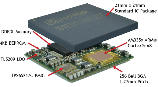
The failure rate for each chip can be found from single chip test data provided by chip supplier. Components are manufactured and tested with standard SC manufacturing processes, therefore increasing System in Package reliability. Using OSD335x -SM for illustration (Fig.1), we find the following cumulative failure rate based on HTOL data on individual chips.
Below is the reported failure rates of individual chips were as follows:
Table 1: Supplier reported FIT rate for IC components in OSD3358- SM at 55C
| CHIP | oC T(STRESS) | SAMPLE SIZE | STRESS HOURS | FAILS | oC T(USE) | FIT AT 55oC |
|---|---|---|---|---|---|---|
| 1 | 130 | 1642 | 1000 | 0 | 55 | 6.1 |
| 2 | 125 | 35681 | 1000 | 1 | 55 | 0.7 |
| 3 | 125 | 139267 | 1000 | 0 | 55 | 0.1 |
| 4 | 125 | 515 | 1000 | 0 | 55 | 25 |
| 5 | 150 | 491 | 1000 | 0 | 55 | 0.3 |
| Total FIT rate for the 5 chips | 32.2 | |||||
FIT rate at any other temperature and a system containing multiple SIPs can be calculated. Table 2 below gives FIT rates at 75C and 85C for a 1 SIP system and a 10 SIP system (Ref. 1)
Table 2: FIT rates at 75C and 85C for a 1 SIP system and a 10 SIP system
| Cumulative FIT all chips (FAILURE IN TIME) | MTBF- YEARS (1 SIP SYSTEM) | MTBF - YEARS (SINGLE SYSTEM 10 SIPS) | |
|---|---|---|---|
| 55 C | < 33 | > 3549 | > 354 |
| 75 C | < 136 | > 845 | > 84 |
| 85 C | < 262 | > 436 | > 43 |
To assess the reliability of chip-package interconnects, and intra-package interconnects the following reliability tests were done.
Table 3: Environmental Stress Tests
| Stress Test (SiP level) | Reference Conditions (Jedec Standards: www.jedec.org) | Sample Size | Result |
|---|---|---|---|
| Preconditioning | JESD22-A113 | MSL3, 245C | 160/0 |
| Temperature Cycle | JESD22-A104 | -40C to +125C 200 cycles | 37/0 |
| Thermal Shock | JESD22-A106 | -55C to +125C 200 cycles | 40/0 |
| Unbiased HAST | JESD22-A118 | 110C/85%RH 264 Hours | 40/0 |
| High Temperature Storage | JESD22-A103 | 150C 500 hours | 40/0 |
3 Comparison of SiP Reliability With an Equivalent System on Board
A discrete-component system-on-board and an equivalent BGA based SiP contain the same IC and passive components. In a SiP the IC components can be in bare die form or previously molded; these are then molded over in SiP. In a discrete-component system-on-board IC components and passives in a system-on-board are soldered and are free standing without encapsulation.
Another important aspect in comparing SiP and discrete-component system-on-board is the chip temperature. SiP can often be designed to keep the chip temperature equal or cooler than discrete-component system-on-board. In such a case SiP based systems reliability can be equal or better reliability than discrete-component system-on-board.
.
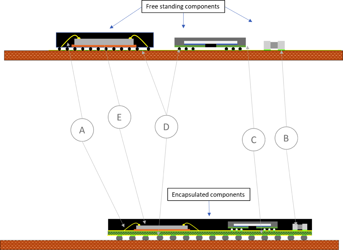
Comparing each of the failure mechanisms for SiP and System-on-Board, we can make the following conclusions:
| FAILURE MECHANISM | DISCRETE COMPONENT SYSTEM-ON-BOARD | SYSTEM IN PACKAGE (SIP) | REMARKS | |
|---|---|---|---|---|
| A | Wire bond failure – Poor Intermetallic Compound (IMC) formation, corrosion. | = | = | SIP packages and discrete component system-on-board use similar assembly process and materials. Thus, the failure rate is expected to be same between the two. |
| B | Passive component (capacitor, resistor) cracking, and passive component solder joint failure. | (--) | (++) | In case of SIP the components are In case of SIP the components are encapsulated because package is molded, this reduces the stress that would have occurred due to flexure of PCB and mechanical shock and vibration. In SIP flexure of substrate is negligible because of the molded section stiffens the substrate. SIP will have a lower failure rate than discrete component system-on-board. |
| C | SMT component solder joint failure | (--) | (++) | In case of SIP the components are In case of SIP the components are encapsulated because package is molded, this reduces the stress that would have occurred due to flexure of PCB and mechanical shock and vibration. In SIP flexure of substrate is negligible because of the molded section stiffens the substrate. SIP will have a lower failure rate than discrete component system-on-board. |
| D | SIP BGA solder joint failure | = / (-) | = / (+) | BGA packages used in both the system on BGA packages used in both the system on board as well as in SIPs use form factors, ball size and ball pitch within the BGA family of packages in the industry. Board level reliability of these BGA packages is well established in the industry. The total number of number of BGA joints in SIP is likely to be lower than the sum of solder joints in discrete component system-on-board; for this reason SIP is likely to have lower failure rate. |
| E | Intrinsic failure rates in Si device, temperature dependent | = / (-) | = / (+) | In SIP as well as an equivalent system on If the temperature of a chip is the same then failure rate is same. If SIPs operate cooler (as in OSD3358) then the failure rate for SIPs will be lower. |
(=) Equal to the other case. (-) Slightly worse the other. (–) Much worse than the other. (+) Slightly better than the other. (++) Much better than the other.)
4 Additional Discussion
4.1 Wire Bond Failures
Wire bonds are used to interconnect chip to package. Bonds can fail due to poor intermetallic joint formation between chip pad and wire, degradation and failure of intermetallics under high temperature, corrosion, and abnormal stress due to poor molding surrounding the joint. Since SiP BGA and individual chips use similar assembly processes and materials, the failure rates are going to be very similar in a discrete package chip on board and SiP BGA.
4.2 Passive Component Failures
Common failure mechanisms for passive components (chip capacitors, resistors) are due to solder joint or component cracking. These occur due to flexure of PCB and shock and vibration. In this case SiPs have a clear advantage. Because SIPs are molded over, they add mechanical stability to the substrate carrying passive components preventing flexure and solder joint and passive cracking. Furthermore, since the solder joints are surrounded by encapsulant or molding compound, they are well-protected and unlikely to fail. Thus a SiP will have lower failure rate for passive component joints compared to a similar system-on-board.
4.3 Solder Joints at PCB Level
In both SiP and system-on-board components eventually get soldered on a PCB. However, the number of solder joints to a PCB in a discrete system is higher than in SiP. This is because in a SiP solder joints are either internal to the package or eliminated altogether in the construction of SiP. For example, the total number of solder joints in a OSD3358-SM is 256 whereas in an equivalent system on board the number of solder joints is approximately 630. Thus the fewer umber of solder joints equate to less opportunities for failure in a SiP.
4.4 Intrinsic Failure Rate in Silicon Devices
Whether in a SiP or system-on-board IC devices’ intrinsic failure rate is dependent on operating voltage and chip temperature. SiP thermal performance is often better than discrete packages in system-on-board. In this case IC would be at a lower temperature than in discrete system on board thus failure rate would be lower.
5 Conclusion
SiP failure rates can be determined from the cumulative failure rate of individual chips. An analysis of different failure mechanisms in SiP and system-on-board shows that SiPs are expected to have as good or better product life compared to system-on-board. The primary contributor is lower failure rate of interconnects in SiPs due to encapsulation. In a properly designed SiP, a cooler operating temperature will further reduce SiP failure rate and increase operating life compared to system-on-board. The analysis shows System in Package gives customers a more-reliable, higher-quality product to put into an end system.
6 References
- W.McPherson, Reliability Physics and Engineering, Time-To-Failure Modeling, 3rd Ed., Springer Publishing (2019)
- Dantu, Murtuza, Welsh, Frantz, “Path to Systems: A SiP of Reliable Advantage—Systems Under Test”, Electronic Design (Jan 30, 2019)
7 Revision History
| Revision Number | Revision Date | Changes | Author |
|---|---|---|---|
| 1 | 2/19/2019 | Initial Release | M. Murtuza |
