Using Ethernet with OSD335x – AM335x System in Package
Published On: May, 24, 2019 By: Eshtaartha Basu
 The Texas Instruments AM335x processor used in the OSD335x Family of System in Package Devices supports up to two independent Gigabit Ethernet ports (10/100/1000 Mbps). This application note will help you quickly get started interfacing an Ethernet PHY with the OSD335x, the AM335x System in Package, Family of Devices. This document will showcase reference designs, which can be used as design examples, make recommendations on layout, device trees and provide tips on debugging AM335x Ethernet issues.
Get updates to this application note and all of our documentation
"*" indicates required fields
Table of Contents
1.Introduction
2.Choosing the Right PHY
2.1.1Reference Designs
2.1.2Additional Ethernet PHYs
3.Design Example / Recommendations
3.1Schematics
3.2Layout
3.2.1Dual Ethernet Example
4.Setting up Ethernet (Device Tree)
5.Debugging Tips
5.1Software Issues
5.2MAC to PHY Connections
5.3PHY to RJ45 Port Connections
5.4Data Errors
6.Revision History of this Document
![]()
![]() A PDF version of this App Note can be found here.
A PDF version of this App Note can be found here.

2 Choosing the Right Ethernet PHY
The AM335x processor within the OSD335x, the AM335x System in Package, Family of Devices contains two Ethernet MAC (Medium Access Control) peripherals that can be used independently or together with an integrated switch. Each MAC supports MII, RMII, RGMII and MDIO interfaces that can be used to connect to an Ethernet PHY (Physical Layer), which in turn is connected to an Ethernet port. This allows Ethernet cables to connect the AM335x to the rest of the network.
Ethernet PHYs are available from many different manufacturers and have a wide range of features. The most significant features to consider when choosing an Ethernet PHY are:
- Power Consumption
- Throughput/Speed – 10/100/1000Mbps
- Package type and size
- Driver support
- Hardware Errata
- Ease of availability
2.1 Reference Designs Using AM335x Ethernet
Reference Designs using the AM335x Ethernet with different PHYs are listed below so that you can choose the best fit for your requirements and jump-start your design.
- AR8035 based OSD3358-SM-RED design from Octavo Systems – https://octavosystems.com/files/osd3358-sm-red-eagle-files/
- AR8035 based C-SiP RED design from Octavo Systems – https://octavosystems.com/files/osd3358-sm-red-c-sip-eagle-files/
- LAN8710 based SBC Reference design from Octavo Systems – https://octavosystems.com/files/osd3358-bas-sbc-reference-design-files/
- AR8031 based Dual Ethernet design from TI Starter Kit – http://processors.wiki.ti.com/index.php/AM335x_StarterKit_Board_Design_Files
- KSZ9031 based Dual Ethernet design shown in Figure 1, Figure 2, Figure 4 and Figure 5 – design files will be published soon.
2.2 Additional Ethernet PHYs
Below is a list of additional Ethernet PHYs from major manufacturers. This is not a comprehensive list but can be used in case there are issues with availability of the PHYs in the reference designs listed above.
- Texas Instruments: http://www.ti.com/interface/ethernet/phy/overview.html
- Microchip: https://www.microchip.com/design-centers/ethernet/ethernet-devices/products/ethernet-phys
- Marvell: https://www.marvell.com/transceivers/fast-ethernet-phy/
- Broadcom: https://www.broadcom.com/products/ethernet-connectivity/
- Microsemi: https://www.microsemi.com/product-directory/ethernet-solutions/3581-physical-layer
For any PHY selection, we strongly recommend that you can purchase the part through a major distributor, such as DigiKey or Mouser, and that the part has plenty of stock available.
3 Design Example and Recommendations for Using Ethernet with the AM335x System in Package
The following figures show an example of a dual AM335x Ethernet design using the KSZ9031 Ethernet PHY to communicate with the Ethernet MAC peripherals on the OSD335x, the AM335x System in Package, Family of Devices. The figures walk through the schematics and layout. Reference design files for this design will be available in the future. Please sign up for documentation updates to be notified when they are available.
3.1 Schematics
When connecting an Ethernet PHY, you need to be aware of the default PHY configuration pull-up / pull-down resistors. Most PHYs utilize a number of pins to set the initial configuration of the device, such as the PHY address on the MDIO bus. It is important that all of these configuration pins are set correctly. For example, in the figure below, you can see the pull-up / pull-down resistors on the RX and LED interfaces that will set the initial configuration of the PHY.
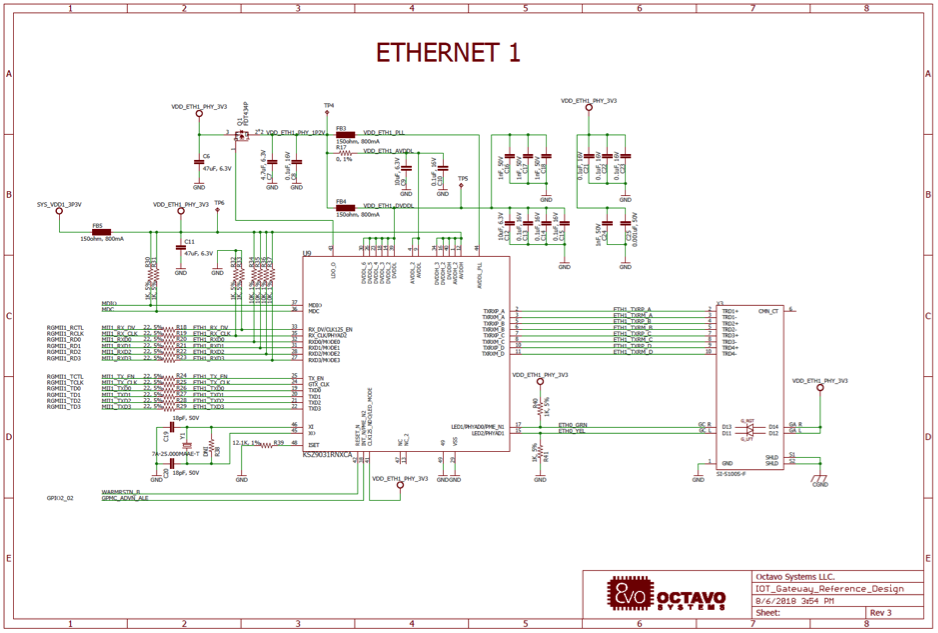
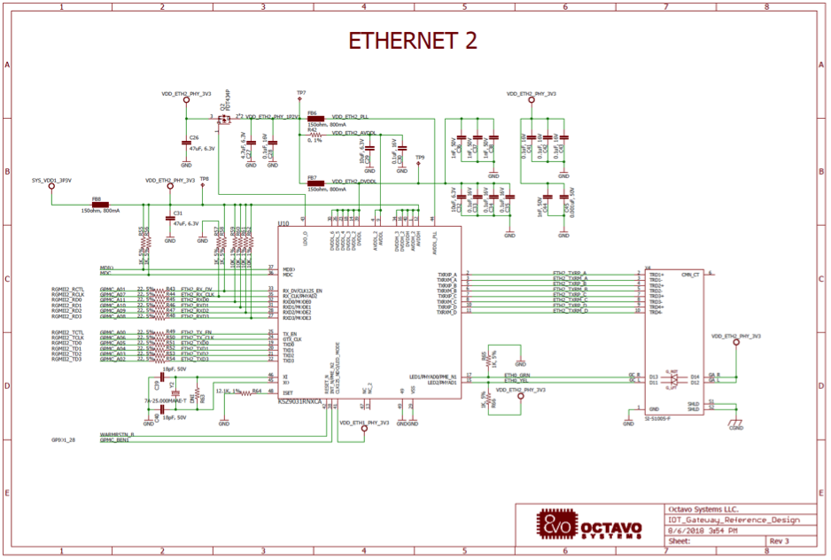
When creating a dual AM335x Ethernet design, it is critical that each PHY have a different MDIO address. This will allow the single MDIO bus to communicate and configure each PHY. Additionally, it is important to know the MDIO address of the PHY since that will be necessary when we set up the device tree for the Ethernet PHY.
3.2 Layout
When laying out an Ethernet PHY, there are two different sets of connections: MAC to PHY and PHY to RJ45 connector (i.e. the Ethernet port). The MAC to PHY connections for the OSD335x Family of devices uses MII, RMII or RGMII. These have a bus speed of 25 MHz, 50 MHz, 125 MHz, respectively. The PHY to RJ45 connections use differential Ethernet signaling in the 10s to 100s of MHz depending on the Ethernet speed required for the link.
The following are some general recommendations for Ethernet PHY layout design:
- Use only 45o/135o angles in traces to avoid signal reflections.
- Trace widths should be constant to maintain uniform impedance.
- Length match TX_CLK, TXDx and RX_CLK, RXDx signals between AM335x and Ethernet PHY. Depending on the interface type, the tolerance for length matching becomes tighter due to the higher bus speeds
- Length match TX+,TX- and RX+, RX- traces between Ethernet PHY and RJ45 connector/magnetics module. We have found that RJ45 connectors with an integrated magnetic module are easier to route.
- Keep the overall trace length between AM335x and RJ45 connector < 75mm.
- If the RJ45 connector (with thru-hole pins) is placed on the top layer, route traces to its pins on the bottom layer to avoid signal stubs caused by the thru-hole pins.
Avoid vias and layer changes for Ethernet traces.
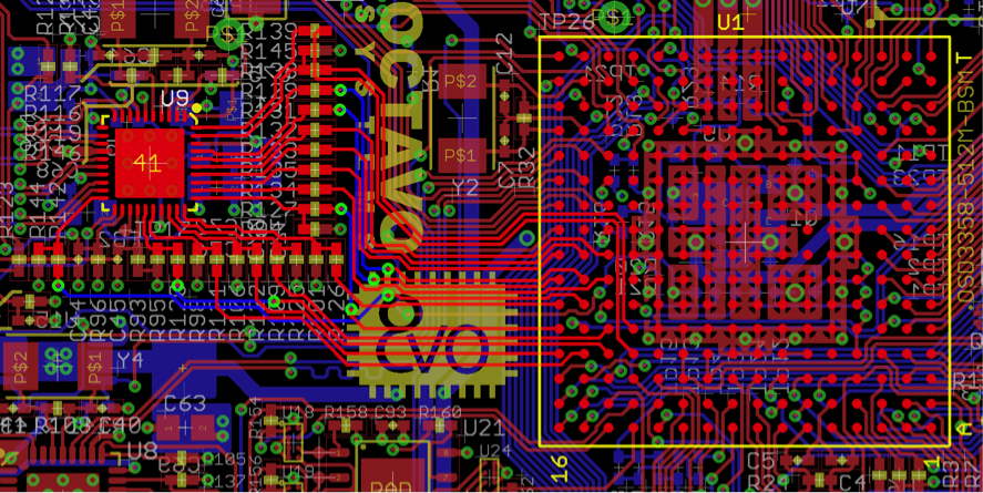
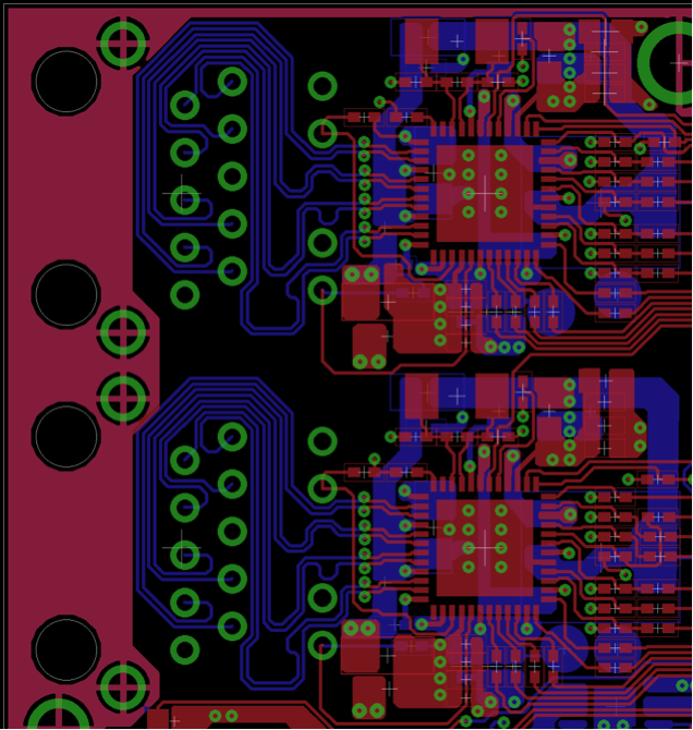
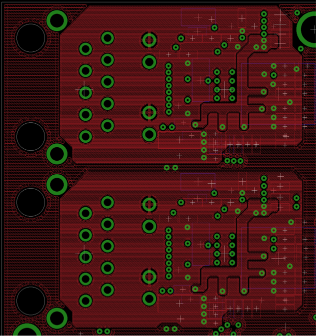
3.2.1 Dual Ethernet Example
On all sides, the first three rows of OSD32MP15x can be easily accessed using 5/5 traces as shown in Figure 4.
3.2 Via Size Background Information
When laying out a dual AM335x Ethernet design, we recommend that you focus on careful placement and routing of a single Ethernet PHY and port. Once that Ethernet PHY and port are placed and routed to your satisfaction, the layout can be replicated easily for the second Ethernet port. You can see an example of this in the figures below when looking at both the signal routing and power layout.
4 Setting up Ethernet (Device Tree)
By default, most Ethernet PHYs follow the IEEE 802.3 (clause 22.2.4) management register set. While each PHY will have vendor specific extensions, the standardization of the management register set means that it is straight forward to set up an Ethernet PHY within Linux to interface with the OSD335x Family of devices. In order to get Ethernet working within Linux, we must properly specify the device tree properties. This section will walk through the information necessary for the Linux device tree.

Most of the device tree declaration for the AM335x Ethernet MAC has been done in the device tree include files for the OSD335x Family of devices (osd335x-sm.dtsi and osd335x-csip.dtsi which can be found at https://github.com/octavosystems/OSD335x-Device-Tree). In the main device tree file for your board, you will need to:
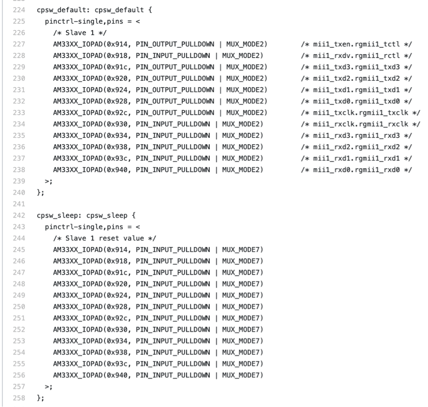
- Define the Pin MUX for each Ethernet Interface: For each of the pins used for a given Ethernet interface, you need to configure the internal pullups/pulldowns and set the pinmux mode (MII/RMII/RGMII). This needs to be done when the Ethernet interface is enabled (i.e. cpsw_default state) and disabled (i.e. cpsw_sleep state). An example configuring Ethernet MAC 1 as an RGMII interface is shown in Error! Reference source not found.. Similarly, you need to configure the pins for the MDIO interface as shown in Error! Reference source not found.
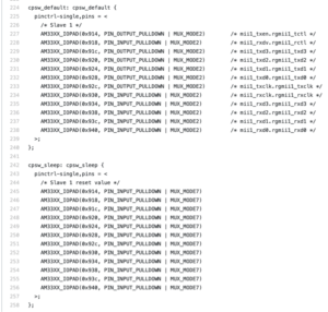

Figure 6 – OSD3358-SM-RED Pin Mux Example- Ethernet MAC 1 as RGMII Interface 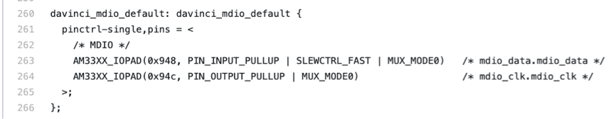

Figure 7 – OSD3358-SM-RED Pin Mux Example- MDIO Interface - Enable the Ethernet MAC: the mac node is disabled by default in the include files. Enable it by setting status = okay using the &mac phandle as shown in Figure 8.
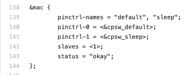

Figure 8 – OSD3358-SM-RED’s &mac phandle Example - Enable the MDIO interface: the davinci_mdio node is disabled by default in the include files. Enable it by setting status = okay using the &davinci_mdio phandle as shown in Figure 9.
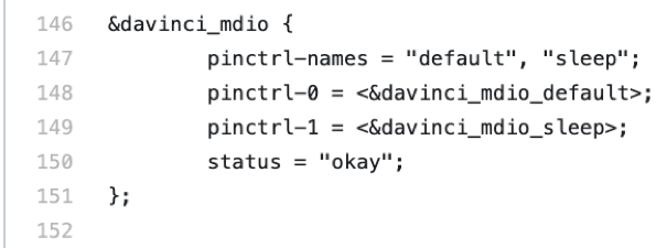

Figure 9 – OSD3358-SM-RED’s &davinci_mdio phandle example - Set PHY ID: As discussed above, each Ethernet PHY has a specific PHY address that is set in hardware using pull-up or pull-down resistors on given configuration pins (PHYADx or similar). This PHY address needs to be provided to the device tree as the phy_id under the given Ethernet interface cpsw_emacx (x = 0 or 1) phandle. If more than one PHY is connected to the AM335x, each PHY should be given a unique address. For example, the phy_id is set to <4> in the device tree snippet shown in Figure 10 which matches the PHY address set using PHY_ADDRx hardware pins shown in Figure 11.
- Set PHY Mode: Based on the MAC protocol that needs to be used to communicate with the PHY, the phy-mode should be set with a value from https://elixir.bootlin.com/linux/latest/source/Documentation/devicetree/bindings/net/ethernet.txt as shown in Figure 10.
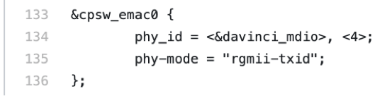

Figure 10 – PHY ID and PHY Mode ![AM335x System in Package Ethernet - PHY_ADDR [2-0] = 0x04 for Eth PHY](https://octavosystems.com/octavosystems.com/wp-content/uploads/2019/05/Figure-11-PHY_ADDR-2-0-0x04-for-Eth-PHY.png)
![AM335x System in Package Ethernet - PHY_ADDR [2-0] = 0x04 for Eth PHY](data:image/svg+xml,%3Csvg%20xmlns=%22http://www.w3.org/2000/svg%22%20viewBox=%220%200%20565%20448%22%3E%3C/svg%3E)
Figure 11 – PHY_ADDR [2-0] = 0x04 for Eth PHY - Additional Properties for Dual Ethernet PHYs:
- Define pin MUX for both Ethernet interfaces (See 1 above).
- Add the dual_emac = <1> property under &mac
- Within the cpsw_emacx (x = 0 or 1) phandle add the property:
dual_emac_res_vlan = <1> for one PHY and
dual_emac_res_vlan = <2> for the other PHY
5 Debugging Tips for Using Ethernet with the AM335x System in Package
Once you have properly configured your AM335x Ethernet design, you still may run into issues. Below are some tips to help debug any Ethernet problems you might encounter. In general, you want to break down the problem:
5.1 Software Issues
If the Ethernet peripheral and PHY declarations in the device tree are not correct, this can cause Linux to improperly or fail to load the Ethernet drivers. To understand the drivers that are loaded during Linux boot, you can use the UART0 console to view the boot messages. If the UART0 console is not available, you can also check the boot log under the “/var/log” directory.
If you get the following errors, it means that there is a mismatch between the PHY address detected by the PHY and the address specified for the phy_id. This could be a typo in the device tree or improper detection of the PHY address based on the pull-up / pull-down resistors on the PHY configuration pins.
1 2 | [ 30.050889] libphy: PHY 4a101000.mdio:04 not found [ 30.106155] net eth0: phy "4a101000.mdio:04" not found on slave 0, err -19 |
In this error message, the Ethernet PHY phy_id was set to “4” in the device tree. However, the PHY could not be detected at address “4”.
5.2 MAC to PHY Connections
To verify the MAC to PHY connections, you can put the Ethernet PHY in loopback mode in which the PHY will route any packets received on the TX interface back to the RX interface without putting the transaction on the PHY to RJ45 port pins. To help with this, we have provided an Ethernet Loopback Test that will allow you to put the PHY in loopback mode. Please refer to the documentation in the zip file for instructions on how to use the software.
5.3 PHY to RJ45 Port Connections
It is difficult to test the PHY to RJ45 Port connections independently. Instead, testing this relies on connecting the RJ45 Port to an Ethernet network. When an Ethernet cable is connected from the RJ45 Port to an active Ethernet network, you should see the link lights on the RJ45 connector come on as the PHY negotiates the capabilities of the network. If you do not see the link lights come on, check that the network is active and try multiple cables to see if there is a PHY to RJ45 Port connection issue or a cable issue.
5.4 Data Errors
Once you have verified the previous connections, if you are seeing poor performance or data errors (this can show up as TX or RX errors when viewing the Ethernet interface using ifconfig), you can do a couple of things:
- Use a tool such as Wireshark (https://www.wireshark.org/) to view the traffic on the Ethernet network from a host computer. This will allow you to see that the board is generating traffic on the network; if the board is receiving proper responses to requests such as ping or DNS requests; or if there are bad packets on the network.
- Use an oscilloscope to view Ethernet signals. Unfortunately, a higher end oscilloscope is required to view the PHY to RJ45 Port connections. However, lower cost oscilloscopes can be used to view the MAC to PHY connections. When doing so, you can look for timing issues (i.e. the clock signal does not align properly with the data signals) or signal integrity issues (i.e. the waveform itself does not look correct).
Additionally, network firewalls can cause issues when testing Ethernet. Be sure that firewalls on your network or host computer are understood and configured so as not to cause issues when testing the Ethernet functionality of your design.
If you are seeing errors, it is always a good idea to re-check your schematic connections, verify the symbol to footprint mapping for your PHY, and reviewing your layout for issues. If you do have any additional questions regarding using the AM335x System in Package together with Ethernet, please feel free to search for answers and post questions on our Forums (https://octavosystems.com/forums/)
6 Revision History
| Revision Number | Revision Date | Changes | Author |
|---|---|---|---|
| 1 | 5/23/2019 | Initial Release | E. Basu |
