What are the differences in ball maps of AM335x and OSD335x-BAS/IND devices?
The ball map of the OSD335x-BAS/IND was designed to match the ball map of AM335x ZCZ package except for a few changes. The following figure highlights the changes that were made to AM335x ZCZ ball map.
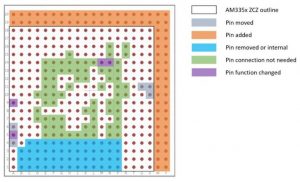
Violet and Grey pins are the only pins that have been moved or functionally changed.
Blue pins (AM335x DDR interface) should be left unconnected.
Green pins (AM335x Power input pins) should be left unconnected or brought out as test points for monitoring.
Orange pins are additional pins added to the package for more functions.
Please refer the datasheet of OSD335x-BAS for their functional description.
The major changes in functionality are listed below.
- V10 (XTALIN): Moved to M20 and renamed as OSC0_IN
- U11 (XTALOUT): Moved to K20 and renamed as OSC0_OUT
- V11 (VSS_OSC): Moved to L20 and renamed as OSC0_GND
- A6 (RTC_XTALIN): Moved to H20 and renamed as OSC1_IN
- A4 (RTC_XTALOUT): Moved to F20 and renamed as OSC1_OUT
- A5 (VSS_RTC): Moved G20 and renamed as OSC1_GND
- A9 (VERFN): Function changed from Voltage Reference to Analog Ground
- M14 (VSSA_USB): Function changed from USB Ground to Digital Ground
- N14 (VSSA_USB): Function changed from USB Ground to Digital Ground
Please refer to to OSD3358-BAS/IND Pin Assignment and Application Differences from Texas Instruments AM3358 document for a detailed list of differences between OSD335x-BAS and AM335x.
OSD335x Family Pin Assignments page lists all the OSD335x pins and their corresponding AM335x pins.
TI’s PinMux tool is also a useful design resource for designing with multiplexed functions of the pins.
