OSD32MP1-RED Getting Started
Published On: February, 22, 2021 By: Greg Sheridan | Updated: February 6, 2023 by Greg Sheridan
Welcome to the OSD32MP1 Reference, Evaluation, and Development Platform (RED), the full featured development platform for the OSD32MP1 System in Package. It provides access to most of the peripherals on the OSD32MP1. It also provides options for easy expandability through industry standard interfaces. This application note will walk you through the process of getting up and running with the OSD32MP1-RED so you can quickly begin developing and prototyping your application.
We will be adding more information to this guide as the platform continues to mature. Make sure you stay up to date on the latest by signing up for updates below.
"*" indicates required fields
Table of Contents
OSD32MP1-RED Overview
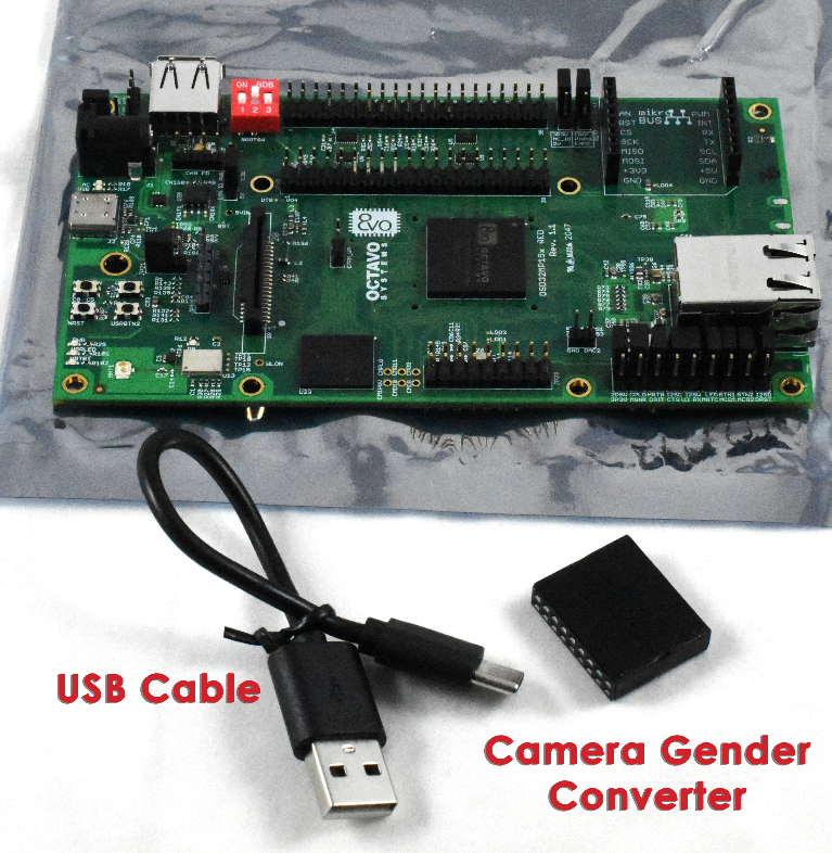
The OSD32MP1-RED package includes the OSD32MP1-RED platform itself as well as a USB-A to USB-C cable and a gender converter for the camera header. The platform comes preloaded with the Octavo Systems Debian Linux Distribution and can be powered over the USB-C Port so this is everything you need to get the platform running. However, there are other items mentioned throughout this application note that would be useful to have.
The completely Opensource OSD32MP1-RED platform features:
| 
|
Full schematics, layout, and other design files for the OSD32MP1-RED can be found here.
Mechanical Information
The OSD32MP1-RED has X and Y dimensions of 5.3″ (13.46 cm) and 3″(7.6 cm) respectively. It also has a number of M3 and M4 holes that can be used for standoffs. The M3 holes are colored in RED and the M4 holes are blue in the image below.
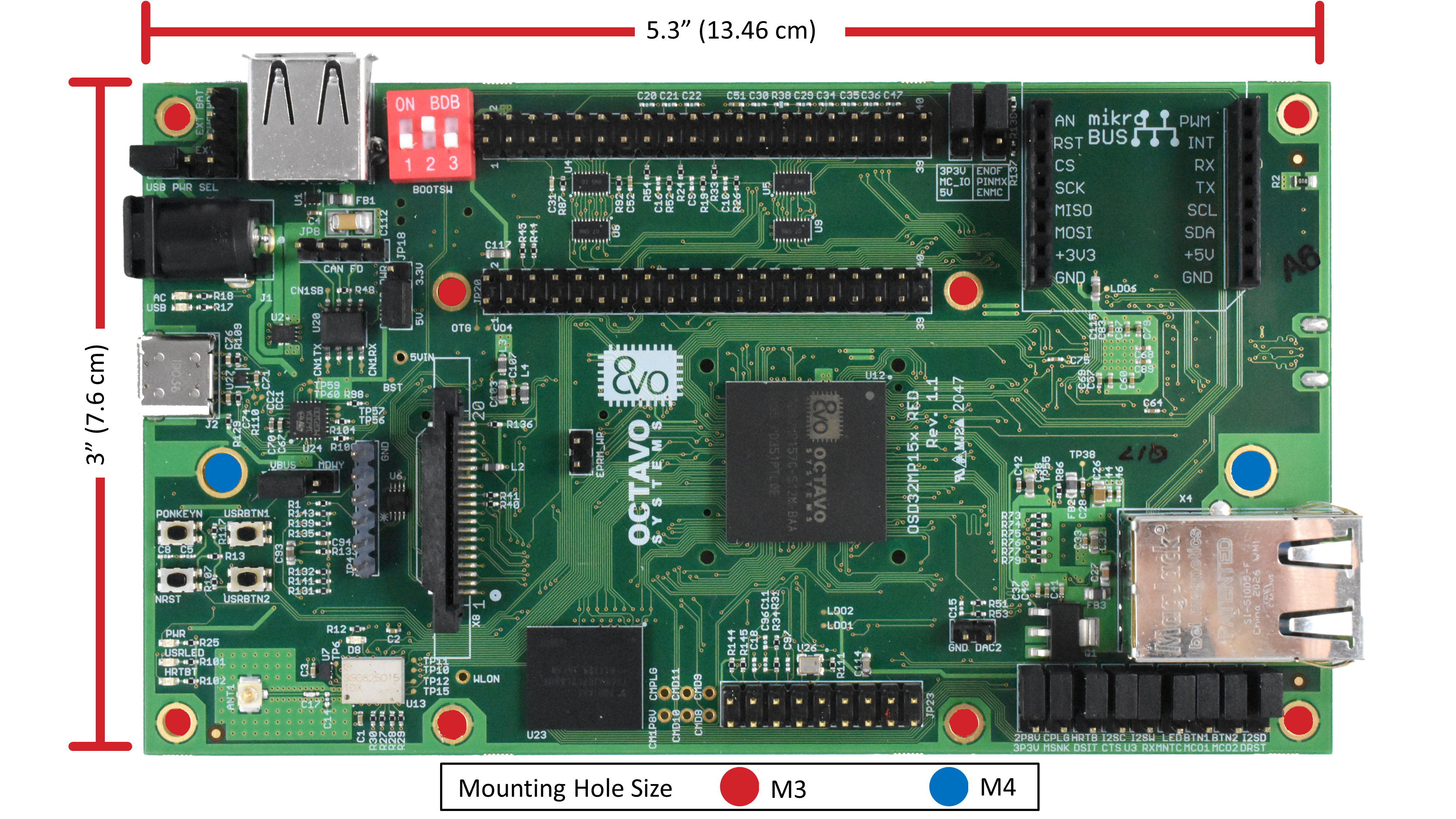
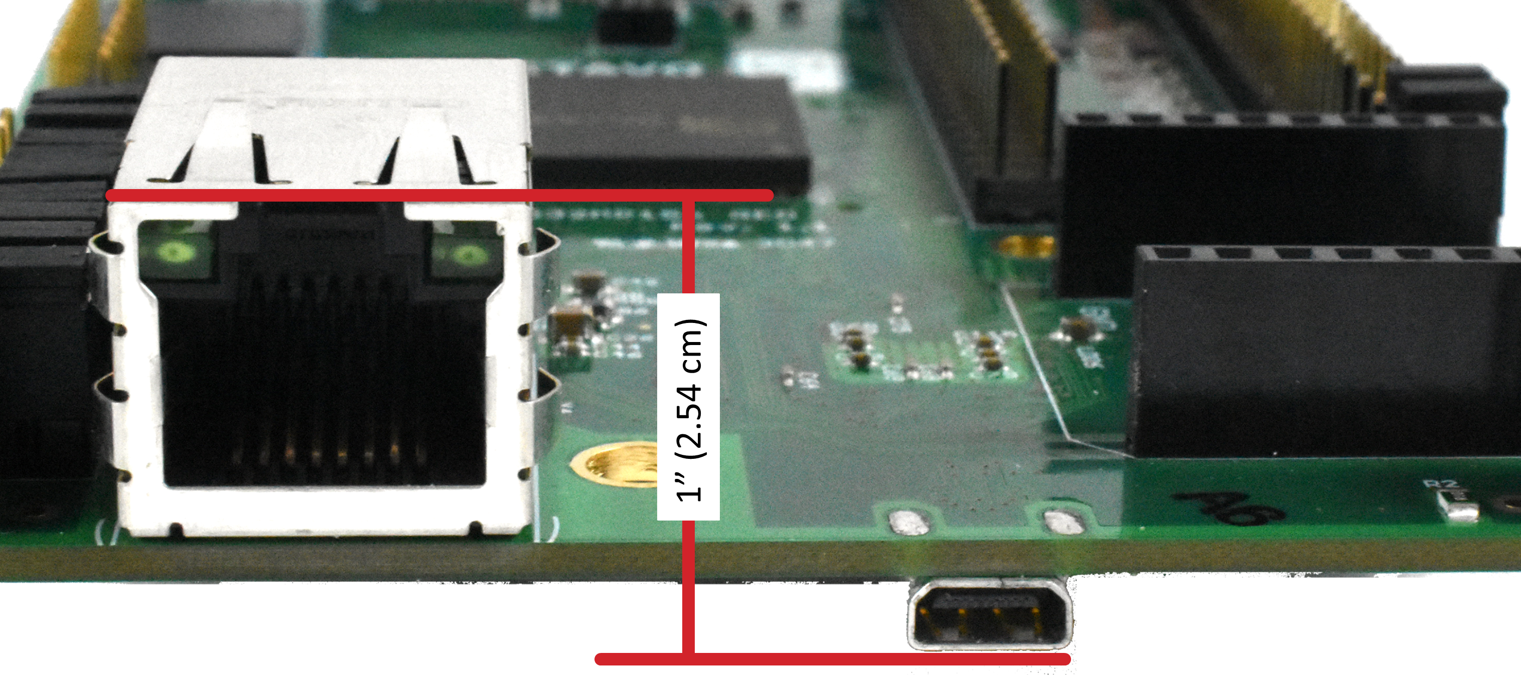
It also has a height in the Z direction of about 1″ (2.54cm) from the HDMI connector on the bottom of the board to the top of the ethernet connector on the top.
OSD32MP1-RED Boot Options
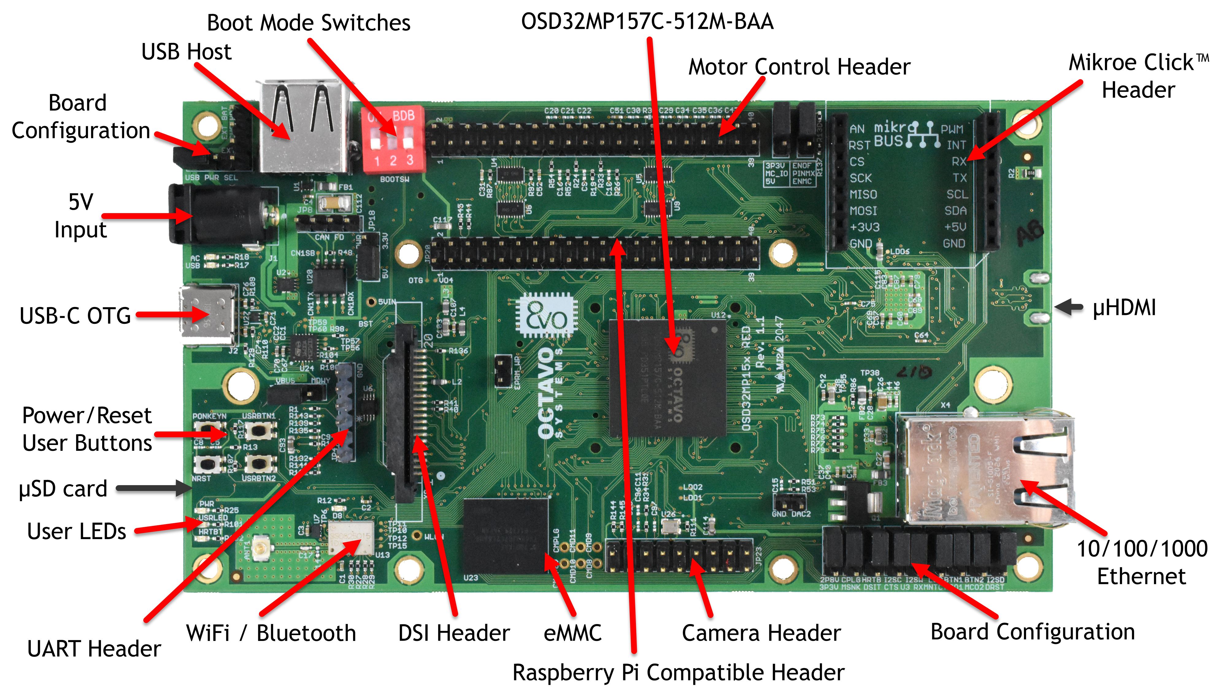
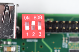
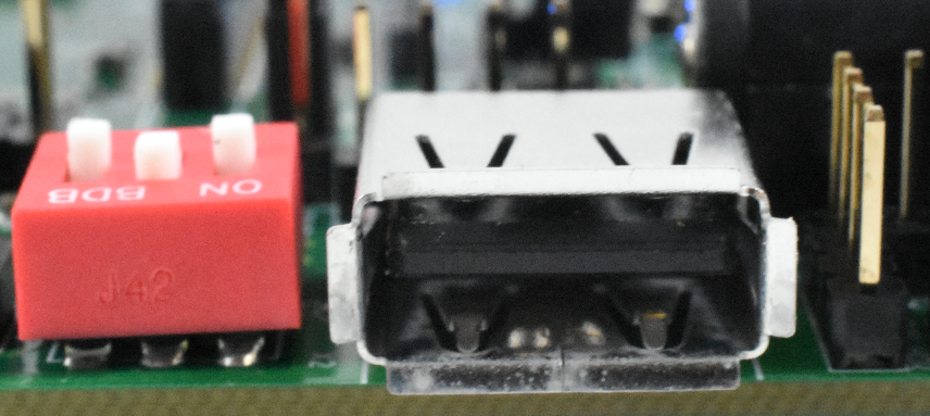
The OSD32MP1-RED by default is set to boot from its onboard eMMC. It can be configured to boot from the SD card or the UART/USB as well. These options are set using the 3-bit switches next to the USB host port.
To boot from eMMC the boot switches must be set to 0, 1, 0 as shown below:
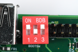
To boot from the SD card the boot switches must be set to 1, 0, 1 as shown below:
All the options can be found in the OSD32MP1-RED Schematics.
OSD32MP1-RED Software Images
Octavo Systems Debian Distribution
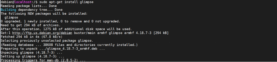
The OSD32MP1-RED comes pre-installed with Debian Linux. This allows you to quickly install and evaluate different applications and tools through the standard Debian package management system like apt.

It also comes loaded with demo applications specifically for the OSD32MP1-RED.
We also have the latest version that can be put on an SD Card that can be found here:
OpenSTLinux Distribution
Since the OSD32MP1 is based on the STM32MP1 from STMicroelectronics, it is compatible with the software provided by ST. To aid with the development of software on OpenSTLinux we provide a OpenSTLinux Starter Image that has been configured for the OSD32MP1-RED. This should be used if you plan to develop using OpenSTLinux and YOCTO.
The image that can be run off an SD card can be found here:
Powering the OSD32MP1-RED
The OSD32MP1-RED can be powered either through the DC barrel connector or the USB-C connector. Both inputs require a 5V DC supply that can provide at least 2A.
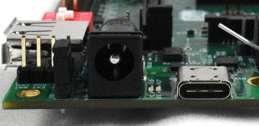
Use a connector with an inner diameter of 2.5mm and an outer diameter of 5.5mm to provide power through the barrel jack. (Here are a couple of examples that we have used: 2A or 3A)
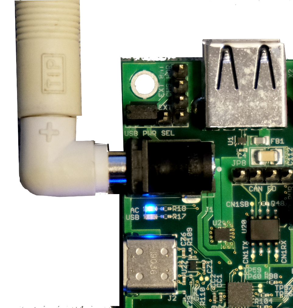
To power the board through the USB Type C connector first make sure the USB-C Power Select Jumper, in the corner between the barrel connector and the USB host connector, is set to position 1-2 as pictured below. More information on this Jumper (JP3) can be found in the schematics.
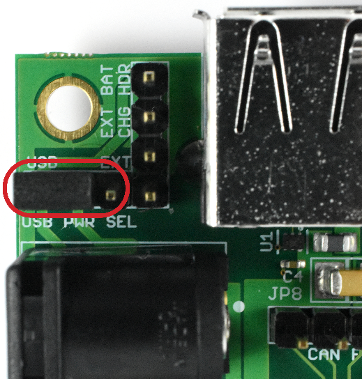
Any USB Type C connector can be used to power the OSD32MP1-RED through the USB C connector.

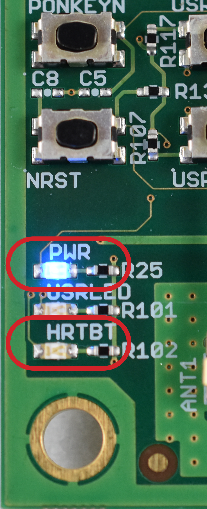
When the board is powered the PWR LED will be illuminated and once it is booted the HRTBT LED will begin to blink.
Connecting to the OSD32MP1-RED
There are two main ways to connect to the OSD32MP1-RED out of the box. Through UART or USB. This section will explain how to connect to the platform via each method.
UART Connection
Connecting through the UART provides the most direct access to the OSD32MP1 device and provides the most information during boot. We highly recommend that you connect to the platform via UART with an FTDI USB to UART cable when you are debugging system start-up and peripheral setup.
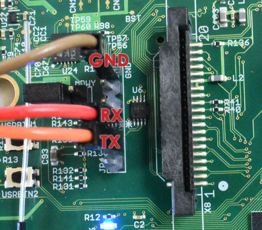
Before powering the board connect to the UART interface:
- Connect the GND of your UART transceiver to the GND pin of the OSD32MP1-RED
- Connect the TX of your UART transceiver to the RX pin of the OSD32MP1-RED
- Connect the RX of your UART transceiver to the TX pin of the OSD32MP1-RED


OSD32MP1-RED UART Connections - Set the baud rate of your UART converter to 115200
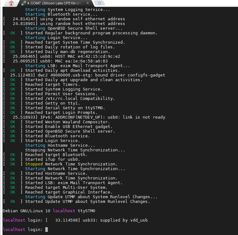
Once connected apply power to the platform and the boot messages will scroll by. Once the boot is complete you will be prompted for the Linux Login. By default, the log in is:
- User Name: debian
- Password: tmppwd
USB Connection
Another option to connect to the OSD32MP1-RED is through USB. Since the OSD32MP1-RED can also be powered via the USB interface this is the process with the least number of cables.
By default, the OSD32MP1-RED images will set up a RNDIS service to provide an ethernet connection to the platform over USB. Once the OSD32MP1-RED is fully booted an SSH client can be used to connect to it. If you believe there is a problem with the platform booting please use the UART connection method described above.
To connect via USB:
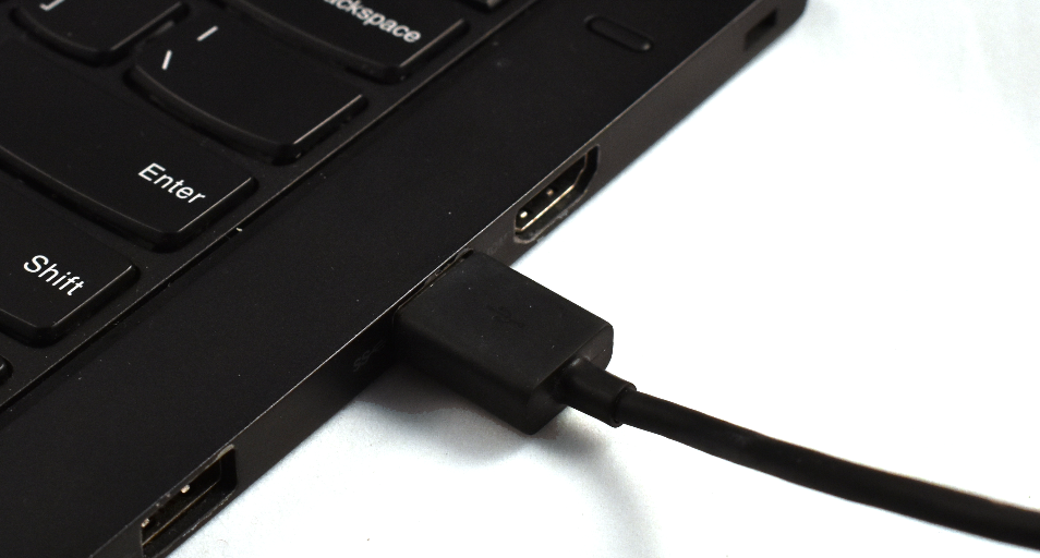
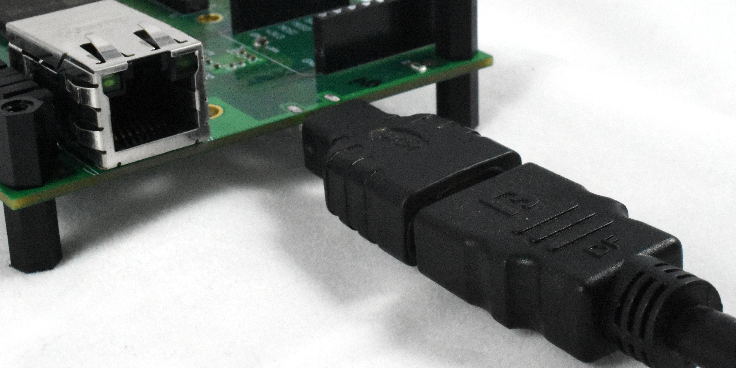
- Plug the USB cable into the OSD32MP1-RED
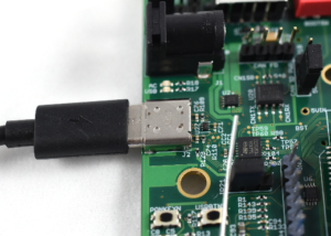

USB-C Connected to OSD32MP1-RED - Plug other end of USB cable into PC
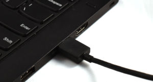

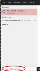
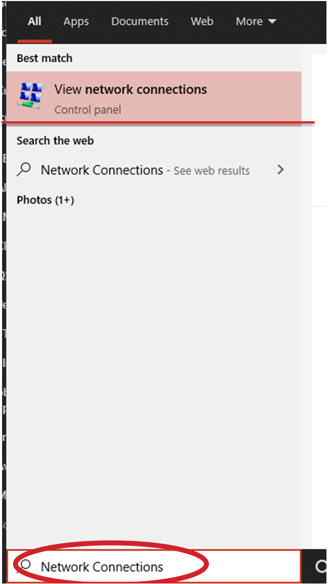
USB Connected to PC - Navigate to the Network Connections on your PC. Type Network Connections into the search box and press Enter.

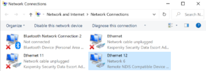
Network Connection Settings - After a few more seconds you should see a new network adapter in your settings called Remote NDIS Compatible Device. This is the USB network connection to the OSD32MP1-RED. (See Troubleshooting section if don’t see new RNDIS device under Network Connections)
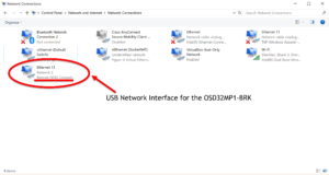

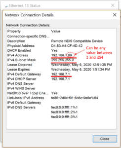
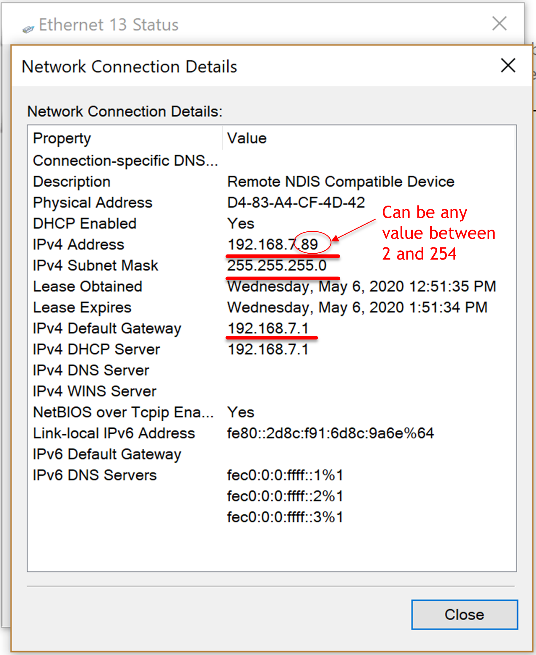
OSD32MP1-BRK RNDIS Interface Note: The OSD32MP1-RED will not show up as a mass storage device in windows explorer by default. You have to go to the Network Connection Settings to ensure the OSD32MP1-RED is connected - Before we can connect to the OSD32MP1-RED we need to ensure the new RNDIS network connection is set up correctly. Open the connection details and ensure that the following properties are set correctly. If not please set them manually ( Following the Ethernet, IPV4 instructions found here.):
IPv4 Address: 192.168.7.XX (XX can be any number between 2 and 254)
IPv4 Subnet mask: 255.255.255.0
IPv4 Default Gateway: 192.168.7.1

PC Network Settings - Now using the program of your choice, you can SSH into the OSD32MP1-RED using the instruction below depending on the image you chose.
Octavo Systems Debian
ssh debian@192.168.7.1
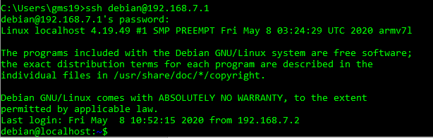

Username: debian
Password: tmppwd - You have now successfully connected to the board and are ready to start running applications!


OSD32MP1-RED Peripherals
The OSD32MP1-RED has many common peripherals that are used in a wide variety of applications. This section will briefly explain how to use them with their default functionality.
Ethernet
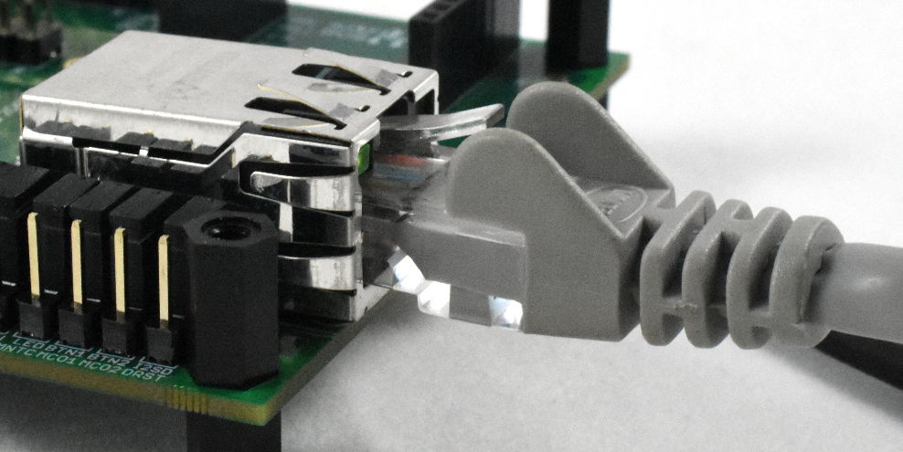
The OSD32MP1-RED has a 1Gbit Ethernet port. This can be used to connect to any network and provide internet access. To use the Ethernet port connect an ethernet cable to the OSD32MP1-RED and to a compatible network switch.
If your network automatically assigns IP Addresses via DHCP the OSD32MP1-RED will automatically receive an IP address.
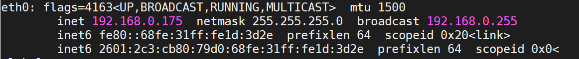
If not you will need to configure the network manually with the standard Debian networking tools described here: https://www.debian.org/doc/manuals/debian-reference/ch05.en.html
USB Host
The OSD32MP1-RED has a USB2.0 High Speed Host Interface that can be used to interface to a wide range of USB devices.
First ensure that your device is supported by the version of Linux that is currently running. Then plug it in. You should then be able to interface with it as normal. Here is an example of a USB Drive.
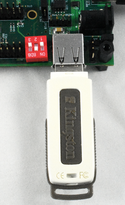
debian@localhost:~$ sudo fdisk -l

Disk /dev/sda: 984 MiB, 1031798784 bytes, 2015232 sectors
Disk model: DataTraveler 2.0
Units: sectors of 1 * 512 = 512 bytes
Sector size (logical/physical): 512 bytes / 512 bytes
I/O size (minimum/optimal): 512 bytes / 512 bytes
Disklabel type: dos
Disk identifier: 0x086aaf0f

Device Boot Start End Sectors Size Id Type
/dev/sda1 * 2048 2015231 2013184 983M c W95 FAT32 (LBA)
HDMI Display
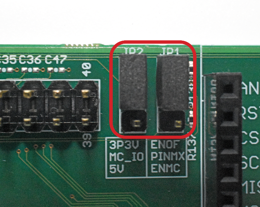
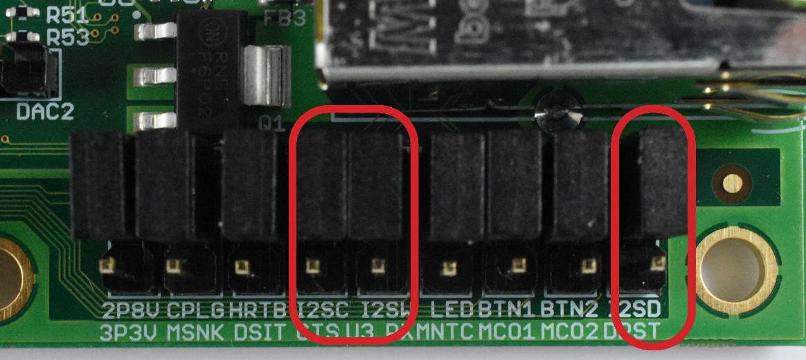
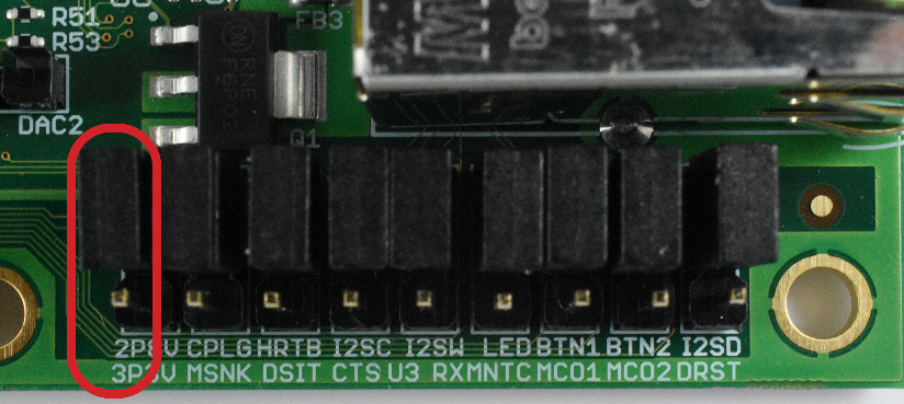
By default, the Linux Images provided my Octavo Systems use HDMI for the display and audio output. To support the widest variety of applications some of the HDMI pins are shared with the Motor Control Header. For HDMI to function properly Jumper JP1 and JP2, next to the Motor Control Header, need to be set to position 1-2 as shown below. More information on these jumpers can be found in the schematics.
Also, for audio to be sent over HDMI Jumpers JP5, JP9, and JP10 need to be set to position 1-2 as seen in the image below. More information on these jumpers can be found in the schematics.
Now plug in a µHDMI cable into the OSD32MP1-RED and the other end into a monitor and you should see the default desktop.
DSI Displays
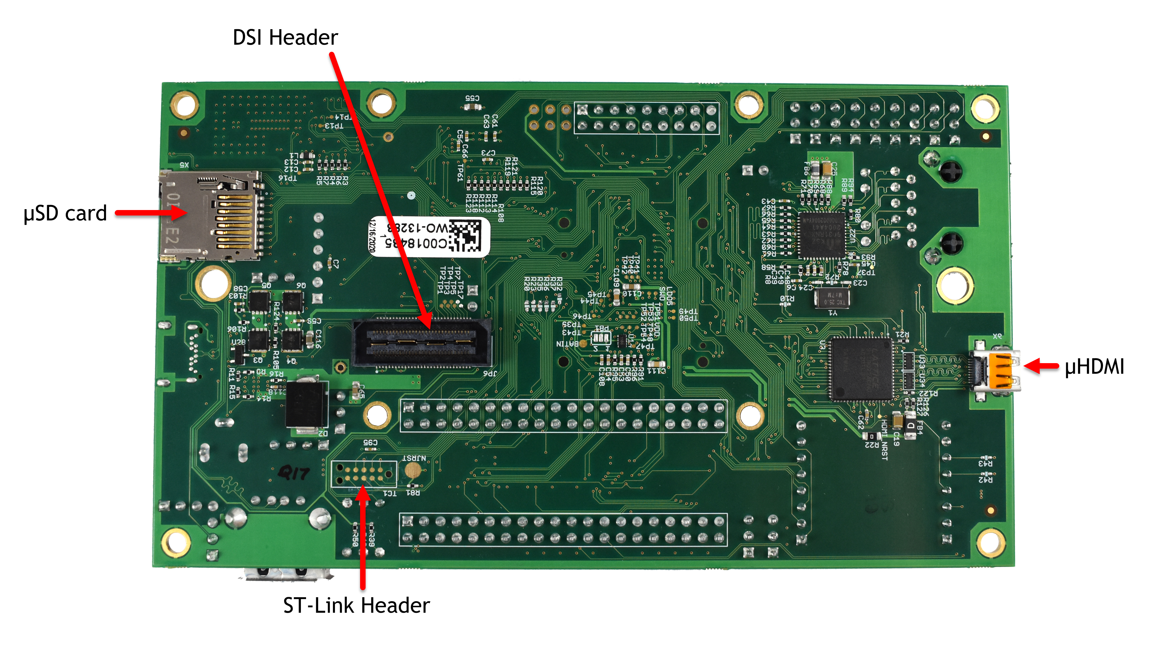
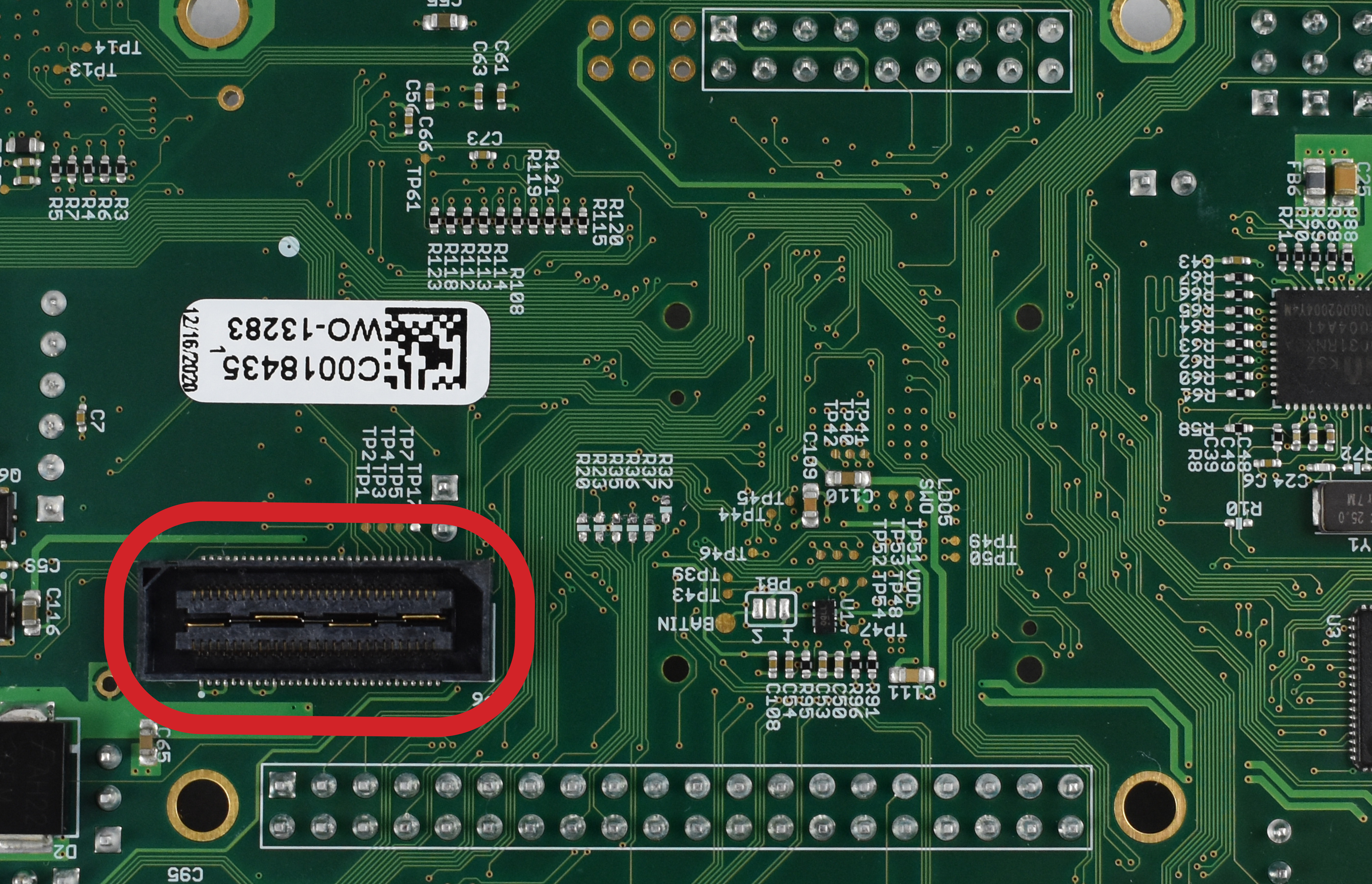
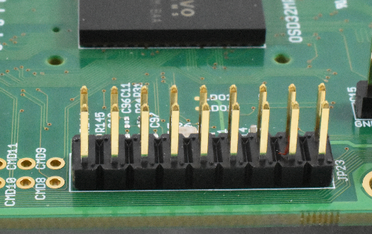
OSD32MP1-RED has 2 DSI connectors, one on the top side of the board and one on the bottom side of the board. The top side DSI connector supports a ribbon cable-based connection to a DSI screen like the one used for STM32MP15x-DK2 board.
|
|
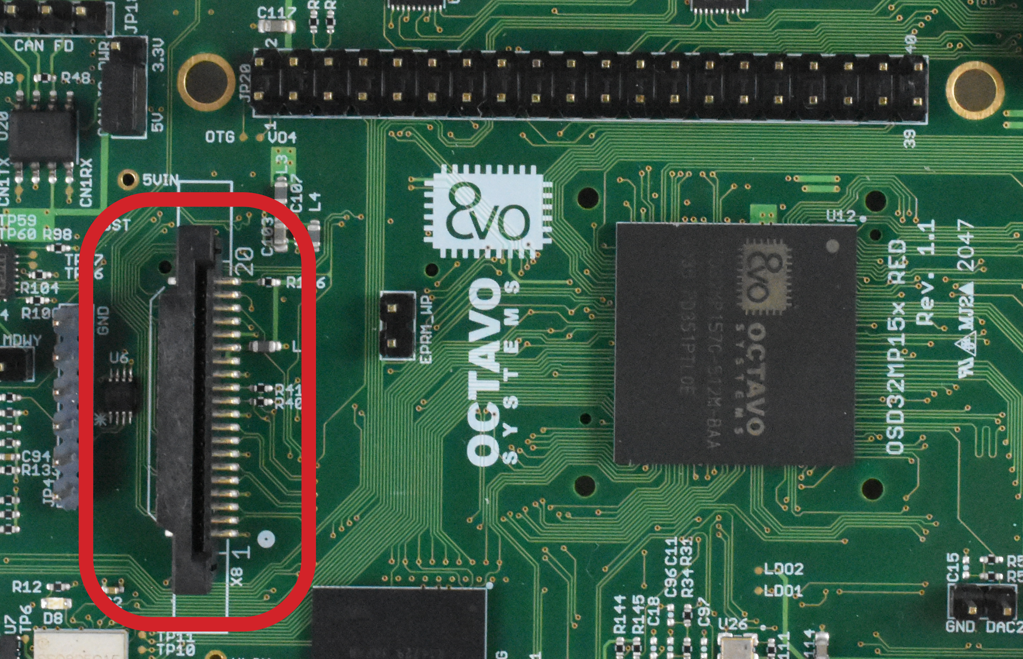

This is a 40 pin connector and does not support DSI screens that use the RaspberryPi 30 pin DSI standard. However, ST has an adapter that will change bottom side DSI connector on the OSD32MP1-RED into a 30 pin DSI ribbon connector that supports the RaspberryPi: https://www.st.com/en/evaluation-tools/b-lcdad-rpi1.html
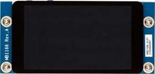
The bottom side DSI connector supports ST’s B-LCD40-DSI1 4-inch LCD screen.
|
|
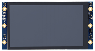
The bottom connector can also support a 7-inch MB1230 1280 x 720p DSI Rocktech LCD screen that is used in the STM32MP157C-EV1:
Please note that the device tree for the RED board must be changed to reflect the presence of the Rocktech DSI LCD panel. The current MP1-RED board device tree setting for the DSI is shown here: https://github.com/octavosystems/OSD32MP1-RED-Device-tree/blob/main/linux-v5.10-r0/stm32mp157c-osd32mp1-red.dts#L772. This will have to be changed to: https://github.com/STMicroelectronics/linux/blob/v5.10-stm32mp/arch/arm/boot/dts/stm32mp157c-ev1.dts#L31 to support the Rocktech DSI LCD panel.
Enabling the DSI Display in OpenSTLinux
When using DSI with the OpenST software release, no modifications are necessary and the board will automatically switch between DSI and HDMI depending on the displays connected. The OpenST software release prioritizes the HDMI connection over the DSI connection.
Enabling the DSI Display in Debian
Using DSI with the Debian software release requires modifications to one configuration file: /etc/xdg/weston/weston.ini In the file, the line “mode=off” must be placed under the appropriate “[ouput]” section. For example, to use HDMI, the configuration file should have:
…
# HDMI connector
# If the hdmi cable is plugged, weston uses the hdmi output (else dsi output).
# Use the command "systemctl restart weston@root" after pluging/unpluging the hdmi cable.
[output]
name=HDMI-A-1
mode=1280x720

# DSI connector
[output]
name=DSI-1
mode=off
transform=180
…
Similarly, to use DSI, the configuration file should have:
…
# HDMI connector
# If the hdmi cable is plugged, weston uses the hdmi output (else dsi output).
# Use the command "systemctl restart weston@root" after pluging/unpluging the hdmi cable.
[output]
name=HDMI-A-1
mode=off

# DSI connector
[output]
name=DSI-1
mode=800x480
transform=180
…
Please make sure that the DSI mode resolution matches your DSI screen.
WiFi
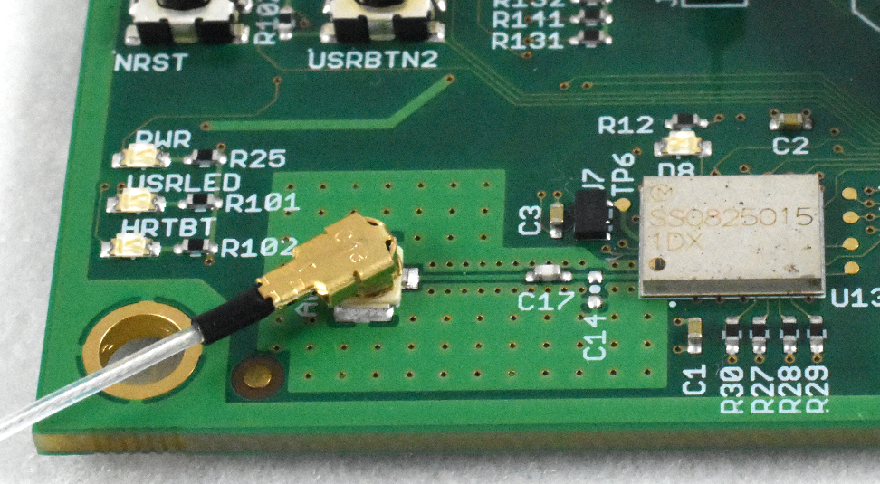
Another option for network connectivity is to use the onboard WiFi Module. In order to use the onboard WiFi Module you will need to connect an u.fl 2.4GHz antenna to the onboard connector. Here is a link to one that we like.
In order to connect to a Wifi Network use the below commands:
- Make sure the WiFi adapter is up:
debian@localhost:~$ sudo ifconfig wlan0 up
- Scan for available networks
debian@localhost:~$ sudo iw dev wlan0 scan | grep SSID
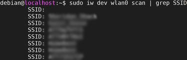

SSID Scan Results - Switch over to the Root User
debian@localhost:~$ sudo su
[sudo] password for debian:
Note: the default password is tmppwd - Enter the network name and password into the wpa_supplicant.conf file
root@localhost:/home/debian# wpa_passphrase <SSID> '<NETWORK_PASSCODE' >> /etc/wpa_supplicant.conf
- Connect to the SSID you specified
root@localhost:/home/debian# wpa_supplicant -B -iwlan0 -c /etc/wpa_supplicant.conf
Successfully initialized wpa_supplicant
- If your network assigns IP addresses automatically through DHCP it should receive an IP address automatically. If it does not refresh the DHCP settings manually:
root@localhost:/home/debian# dhclient -r wlan0
root@localhost:/home/debian# dhclient wlan0
You can learn more on how to control the WiFi interface in Debian here: https://wiki.debian.org/WiFi/HowToUse#Command_Line
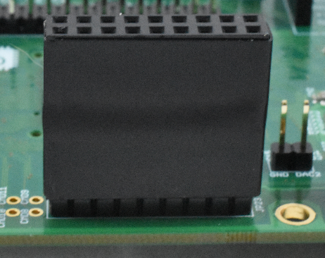
Camera Header
The OSD32MP1-RED has a camera header that can be used to connect Parallel Interface Cameras. Since there are a wide range of cameras available the OSD32MP1-RED provides options to support many different camera options.
The first option is to use 2.8V or 3.3V cameras. This option is set via Jumper JP16. Position 1-2 is 2.8V and position 2-3 is 3.3V. By default, it is set to 2.8V as seen in the image below. For more information on JP16 please see the schematics.
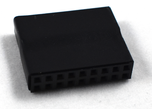
We also provide an adapter to allow you to use a camera with either a male or female adapter.
Demo Applications
The OSD32MP1-RED Debian Distribution comes preloaded with applications to demonstrate the functionality of the board and provide a starting point for your application development. This section will introduce you to the different applications and how to use them.
On Board Video Demo
This is a simple demo that plays a short introduction video that is stored locally. To run:
- Ensure the Jumpers are set as described in the HDMI Display Section
- Connect the OSD32MP1-RED to an HDMI Display with Speakers.
- Power the board as discussed above.
- Connect to the board as discussed above.
- Navigate to the Debian User Root Directory
debian@localhost:~$ cd /home/Debian
- Launch the Demo:
debian@localhost:~$ sudo ./demo_video.sh
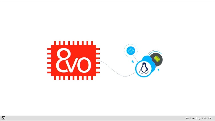
- The Video Should now play

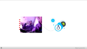
OSD32MP1-RED Introduction Video Playing Note: If using Debian version 3.0 audio over HDMI has been disabled.

Camera Demo
This application utilizes a camera module based on the OV5640 Image Sensor connected to the OSD32MP1-RED Camera interface. It captures video from the Image Sensor and displays it on the Display. We used this camera module which can be purchased from Amazon.
- Connect the Camera Module (using the adapter if needed):
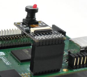
Camera Connected to OSD32MP1-RED - Power the board as discussed above.
- Connect to the board as discussed above.
- Navigate to the Debian User Root Directory
debian@localhost:~$ cd /home/Debian
- Launch the Demo:
debian@localhost:~$ sudo ./demo_camera.sh
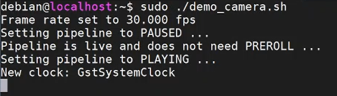

OSD32MP1-RED Camera Demo Console - You should now see the input of your camera on the display
OSD32MP1 Camera Demo


Troubleshooting
This section will provide solutions to potential minor roadblocks might come across while getting started with OSD32MP1-RED.
OSD32MP1-RED shows up as "Other Device" under Windows Device Manager
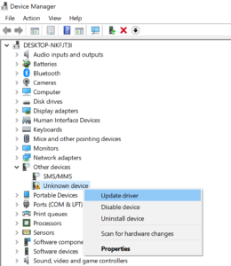
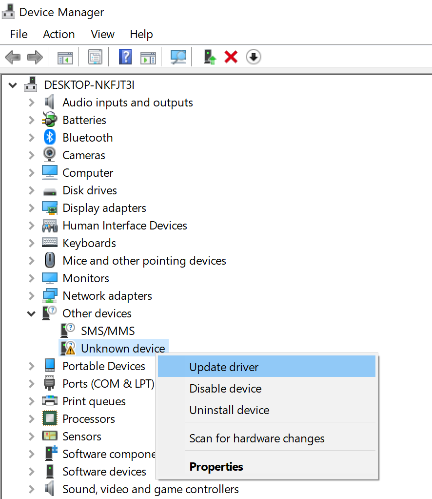
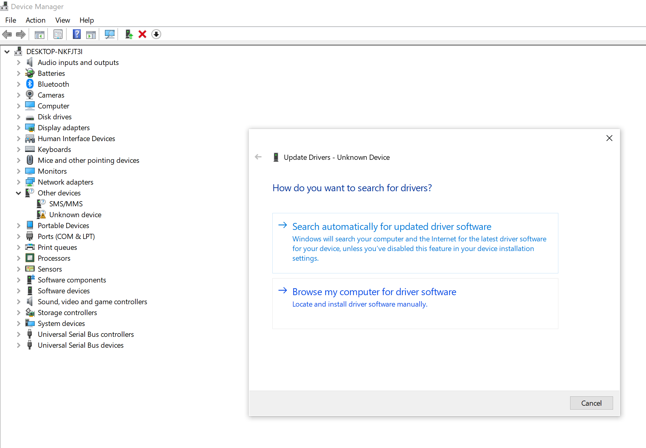
If the OSD32MP1-RED does not show up as Remote NDIS Compatible Device under Network Connections, look for new devices under Device Manager. You may find OSD32MP1-RED under “Other Devices”. To resolve this issue:
- Right click on the Unknown device > Update driver

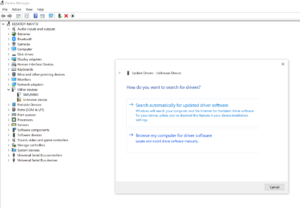
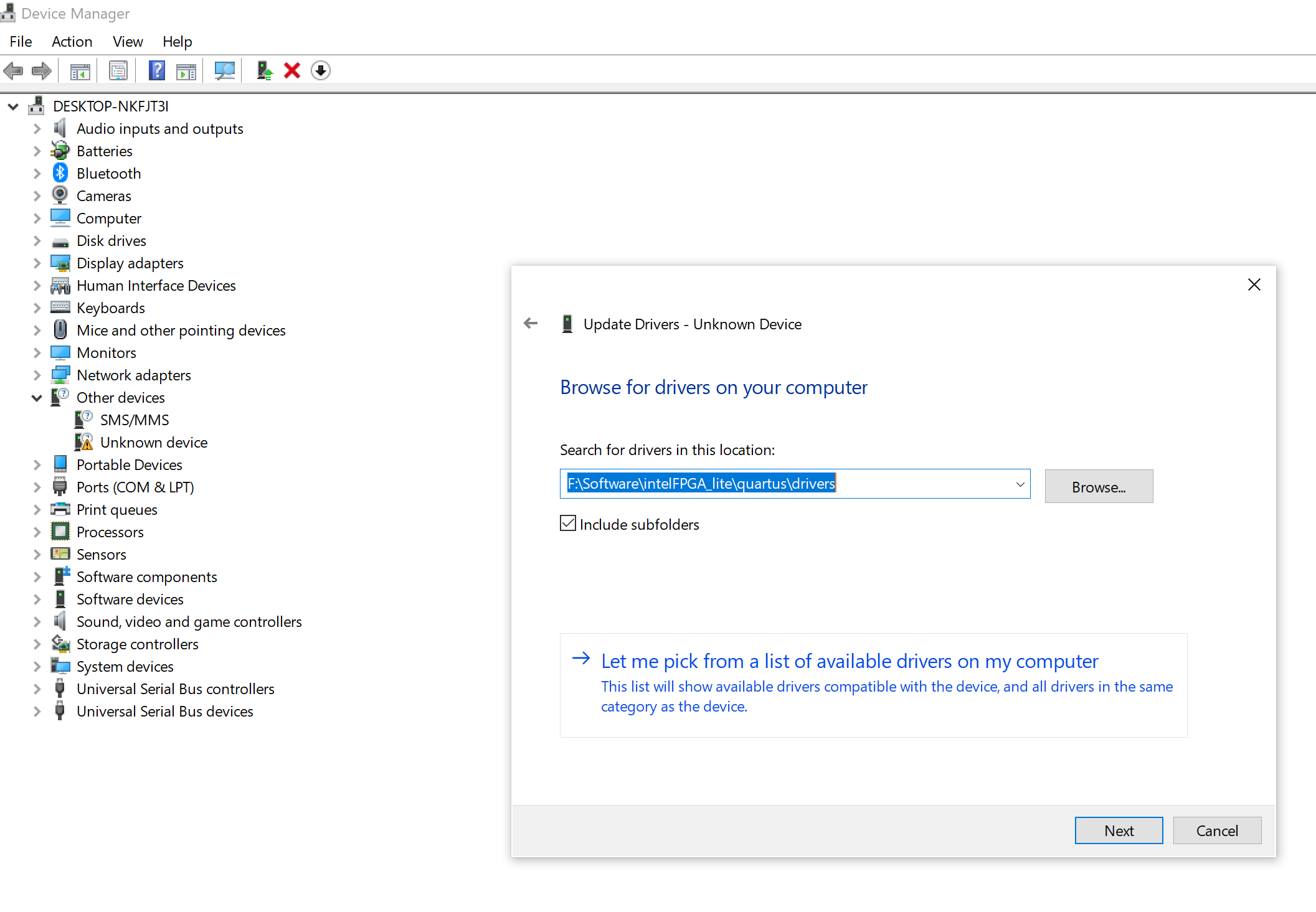
- Click on Browse my computer for driver software

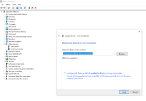
- Click on Let me pick from a list of available drivers on my computer
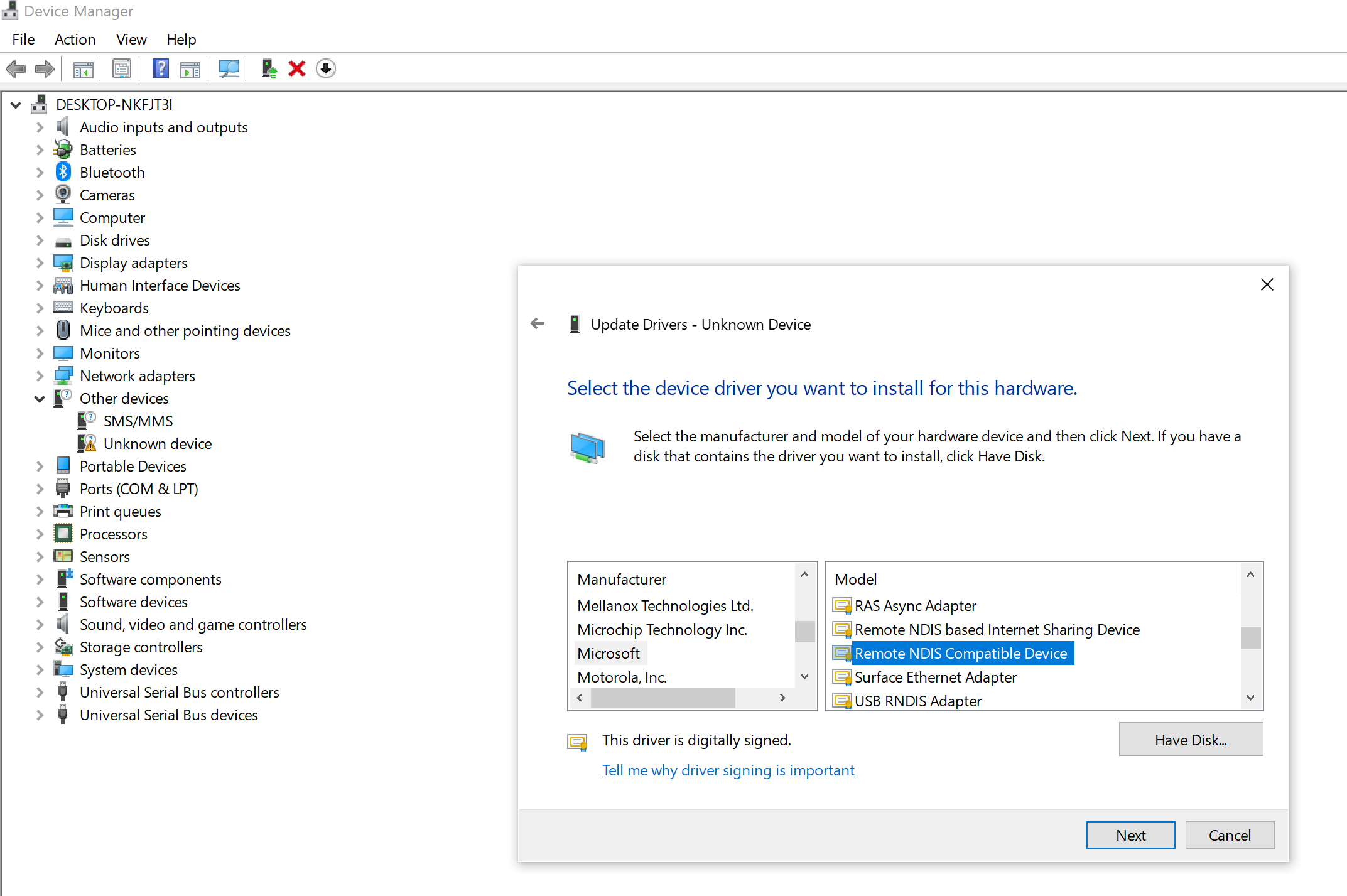
- Choose Network adapters and press Next
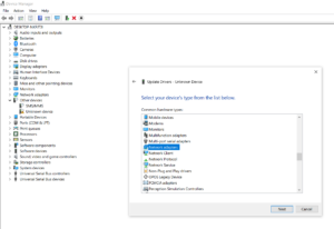

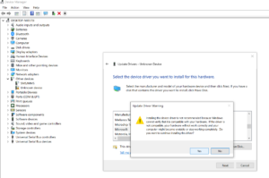
- Choose Microsoft under Manufacturers > Choose Remote NDIS Compatible Device and press Next


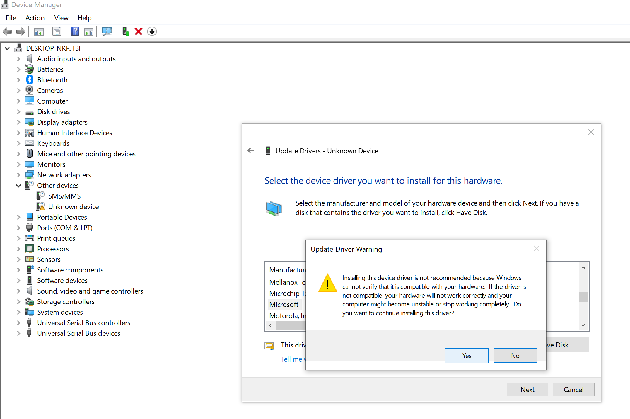
- Click Yes for Update Driver Warning

- OSD32MP1-RED should now show up as Remote NDIS Compatible device under Network Connections


Revision History
We will continue to update this application note to provide more information and more examples. Sign up below to be notified when we update this guide.
"*" indicates required fields
| Revision Number | Revision Date | Changes | Author |
| 1 | 02/15/2021 | Initial Revision | Greg Sheridan |
| 2 | 03/29/2021 | Added Examples of AC Power Supplies | Greg Sheridan |
| 3 | 09/16/2021 | Added Reference to the eMMC flashing forum post | Greg Sheridan |
| 4 | 04/15/2022 | Added Information on using the DSI Connectors | Eshtaartha Basu, Erik Welsh |
